
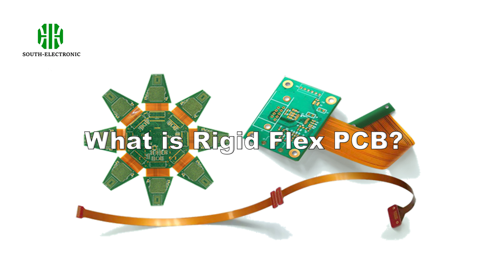
Imagine your medical device fails during surgery. Loose connectors or weak joints could cause this disaster. Rigid flex PCBs solve these critical challenges by merging solid and bendable circuits. Your next innovation deserves this defense against failure.
We choose rigid flex PCBs[^1] for high-reliability systems[^2] needing compact layouts in harsh conditions. They remove soldered joints and connectors, cutting failure risks while boosting signal quality[^3]. Lighter products with stable performance emerge from this hybrid solution.
Now let’s examine the three core aspects shaping this technology’s value. Without them, design flaws could break your project budget and deadlines.
What are the capabilities of rigid flex PCB?
Picture a drone control board cracking mid-flight. Vibration kills traditional setups, but rigid flex endures bending stress. This supports extreme environments.
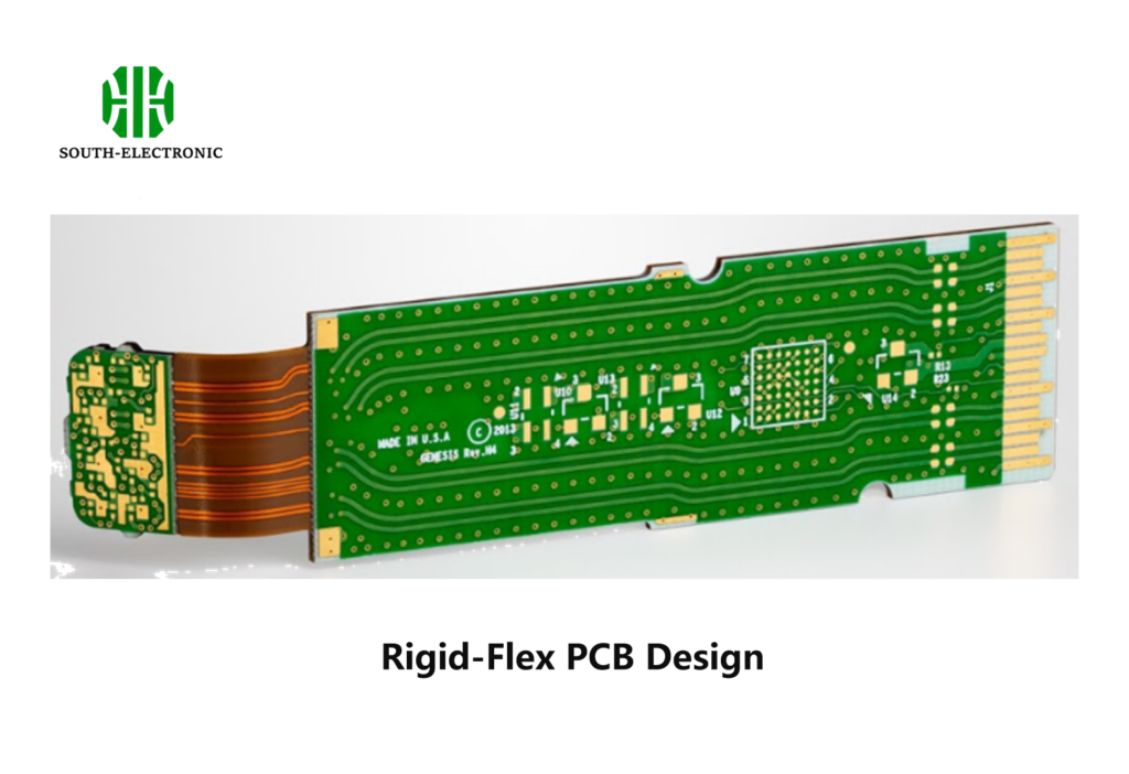
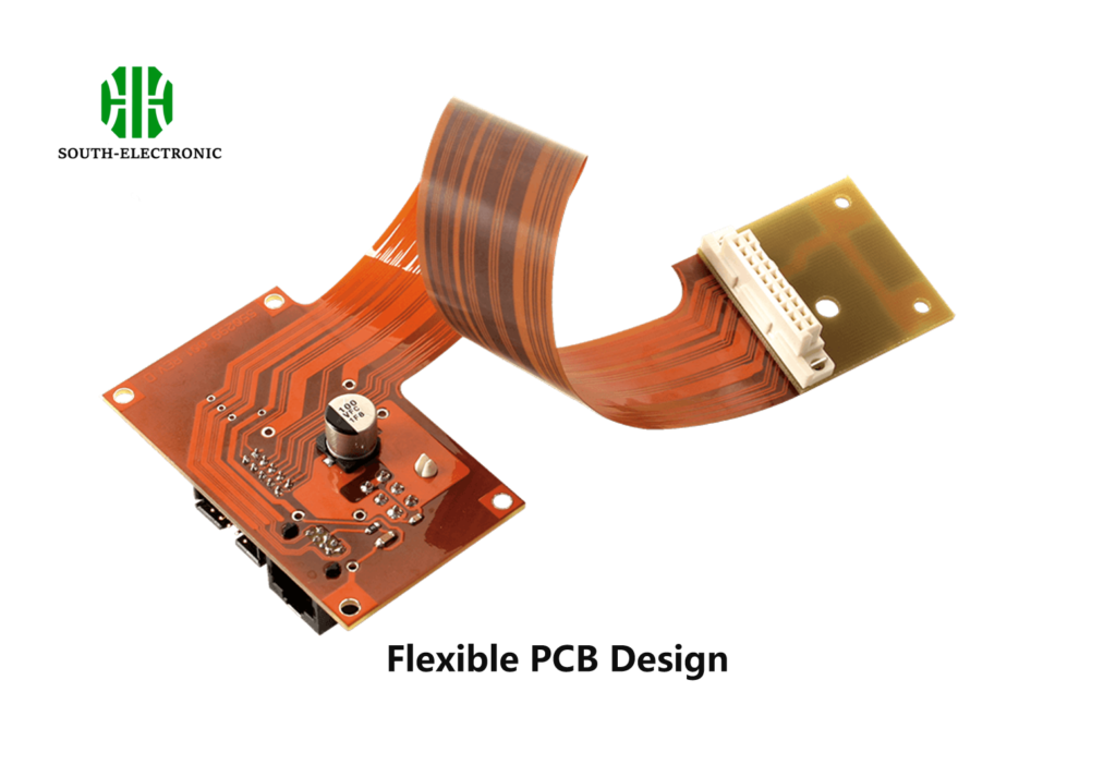
Rigid flex PCBs unite rigid sections (for component stability) and flexible pathways (for 3D movement). Their combined structure enables tighter designs while eliminating cables between boards. Continuous ground planes improve signal integrity across moving joints.
Key strengths in demanding applications
| Performance Area | Traditional PCB Limitations | Rigid Flex Advantages |
|---|---|---|
| Space Utilization | Bulky connectors waste space | Zero-connector design, 90% space reduction |
| Reliability | Solder joints fracture under stress | Monolithic circuits with dynamic bending endurance |
| Environmental Resistance | Failures in high-heat/vibration zones | Survives humidity, thermal shock through flex adhesion |
| Signal Quality | Noise risks at interconnect points | Uninterrupted impedance control between zones |
Rigid flex boards replace multipart systems with unified stacks. The rigid zones host chips requiring firm support. Flex tails twist through tight casing curves, like in wearable monitors. This fusion enables dynamic movement with component-level precision—crucial for folding displays or aircraft controls. Medical implants need this reliability. Complex junction failures drop by 40% without soldered connectors. Flex zones withstand 200,000+ bend cycles, while rigid sections act as heatsinks. This combination beats both solutions alone. Weight savings up to 60% matter in aerospace R&D. Our consumer electronics clients cut field failures using hybrid designs.
How complex is rigid flex PCB manufacturing?
Think about a failed Mars rover circuit. Poor flex layer alignment causes these million-dollar losses. Lamination mistakes trigger costly delays.
Producing rigid-flex PCBs is intricate. Skillful bonding of dissimilar layers needs precise pressure control. Drilling fragile flex areas increases error rates. Complex circuitry across rigid-flex borders demands expert designers.
Manufacturing challenge levels
| Process Stage | Difficulty Factors | Critical Measures |
|---|---|---|
| Material Stacking | Thermal mismatches rigid/flex layers | Autoclave lamination at controlled expansion rates |
| Hole Drilling | Cracks in flexible bases | Laser drilling under 0.5mm accuracy |
| Plating | Uneven coating near rigid-flex edges | Pulse electroplating cycles with 0.2-mm voids avoidance specs |
| Testing | Circuit breaks at transition points | Automated optical inspection (AOI) + dynamic bend tests |
First, operators layer polyimide flex cores with epoxy rigid sheets. Thermal expansion differences require slow autoclave stages to prevent delamination. Micron-level accuracy creates electrical paths between zones—misalignment risks shorts. Gold plating on folds needs uniform thickness for bend resilience. Static shocks harm thin traces during handling. Blind via holes in fold zones weaken structure if mispositioned. Prototypes demand 6+ weeks versus 3 weeks for regular PCBs. Prepreg resin control prevents oxygen voids between layers. Finished boards undergo repetitive bend test cycles mimicking end use—we reject units showing microcracks under magnification. Automated optical scanners flag any angle deviation beyond 0.1 degrees in stiffener placements. While complex, reputable partners manage these risks with rigorous tolerance protocols.

What factors affect rigid flex PCB cost?
A startup’s delayed launch shows why cost matters. Unexpected design updates and material shortages cause budget explosions.
Layer count impacts rigid flex PCB costs most significantly. Flex materials cost 4× rigid boards. Microvias or special finishes (like ENIG) add fees. Setup expenses dominate small-batch pricing.
Primary cost drivers breakdown
| Cost Factor | Price Influence Range | Example Impact |
|---|---|---|
| Layer Quantity | +25-50% per added layer | 8-layer stacks double 4-layer costs |
| Surface Finish | $3-15 per square foot extra | Gold plating over HASL adds durability but 30% fees |
| Testing Intensity | 15-60% of base price | Military-grade thermal cycling doubles checks |
| Batch Volume | Setup costs split across units | Ordering 100 vs. 500 units halves per-piece setup fees |
| Tolerance Tightness | +$250 per design hour | ±0.02mm bends > standard (±0.05mm) require tool recalibration |
Material fees grow fastest. Gold plating for flex contacts outlasts tin but costs 30% more. Polyimide flex cores run $10/sq ft—5× FR4 rigid boards. Thin copper traces increase precision etching expenses. We see specialty adhesives adding 20% per stackup. Complex hole patterns amplify drilling times; 20µm small vias triple drill-head consumption. Testing scales costs too. Each extra bend-cycling stage adds 4-7% for reliability validation. Labor-heavy designs with organic shapes hike engineering charges; aerospace projects incur constant blueprint changes. Proto 50-unit batches charge setup fees transforming economical above 500 units. Silkscreens in bend zones require specialized inks costing 70% more. Minimizing these factors balances budgets without compromising mission-critical durability.
Conclusion
Rigid flex PCBs deliver critical advantages for compact, reliable electronics facing physical stress—just choose proven partners to control costs and complexities.
[^1]: Explore the advantages of rigid flex PCBs for compact and reliable electronic designs.
[^2]: Learn about the characteristics that make high-reliability systems essential in critical applications.
[^3]: Understand the importance of signal quality in ensuring optimal performance of electronic devices.

