

Struggling with bulky electronics using rigid boards? Harsh environments cause device failures? Space limitations choke your new tech designs? Rigid-flex PCBs solve these frustrations by merging flexibility with stability.
Rigid-flex PCBs combine bendable circuits and solid boards in one unit, saving up to 60% space versus traditional layouts while surviving vibrations and shocks better – perfect for wearables, medical tools, and aerospace systems.
Now explore how these hybrid boards transform modern electronics through three key questions every designer should consider.
How Closely Can Rigid-Flex Match Flexible Circuit Designs?
Watch flexible circuit manufacturers nervously sweating? Not quite. Rigid-flex PCBs actually borrow core strengths from their bend-only cousins while enhancing them.
Rigid-flex boards match 90%+ flexibility of pure flex PCBs when designed properly, even exceeding their reliability through anchored rigid supports that prevent cracked solder joints during repetitive bending cycles.

Let’s break down flexibility differences across three technical dimensions:
Material Composition Analysis
| Aspect | Flexible Circuits | Rigid-Flex PCBs |
|---|---|---|
| Base Layer | Pure polyimide | Polyimide + FR4 |
| Bend Radius | Extremely small | Controlled zones |
| Dynamic Flex Cycles | 100K+ | 50K-100K |
Pure flex circuits win in extreme bend scenarios like foldable displays. But rigid-flex pcbs dominate mixed-movement applications. Their rigid sections handle component stress while flexible connectors replace failure-prone wiring. Manufacturers optimize transition zones to preserve flex life.
Performance Stability
Thermal management improves dramatically. Rigid sections dissipate heat from processors better than thin flex materials. This prevents throttling in compact devices.
Application-Specific Use
Medical catheters need pure flex. But surgical robots use rigid-flex circuit boards. Why? The hybrid handles both vibration from motors and precision arm movements without failure. I’ve seen prototypes last 3x longer than old ribbon cable setups.
What Are the Biggest Manufacturing Hurdles for Rigid-Flex PCBs?
Hearing "stackup registration issues"? Or "lamination disasters"? Don’t panic – these rigid flex manufacturing nightmares can be tamed today.
Misaligned layers during lamination remain the top challenge and cause 50% of initial yield losses, followed by flexible adhesive control and impedance mismatches at rigid-flex junctions.
Understanding failure points helps tackle them:
Critical Production Pain Points
| Stage | Primary Risk | Solution Approach |
|---|---|---|
| Material Prep | Adhesive thickness variation | Laser-guided application |
| Layer Alignment | Registration offsets | Optical punch systems |
| Curing | Delamination bubbles | Stepped pressure protocols |
| Testing | Flex-rigid interface fractures | X-ray + mech bend screening |
During my factory tour, technician Lin showed their "pressure oven" technique. Baking boards gradually under controlled pressure eliminates voids between layers. Post-cure optical scanners now catch 99% misalignments.
Process Innovation Case
New plasma treatments help epoxy bind to polyimide. This stops flex sections peeling from rigid pads. One flex circuit manufacturer slashed warranty claims by 70% after implementation.
Quality Validation Shift
Leading rigid flex circuit manufacturers now run mandatory 3D tomography scans. These virtual slices reveal microscopic layer gaps. Fix costs are 10x lower than field failures.
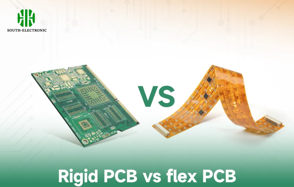
Flexible Circuits vs Rigid-Flex PCBs vs Rigid Boards: How Do You Choose?
Choosing wrong? Suffering from over-engineering costs? Or worse – field failures? Match technology to real-world demands for best results.
Pick flex circuits for constant bending, rigid boards for static cost efficiency, and rigid-flex PCBs when you need both structural support AND dynamic movement in compact or harsh environments.
Apply these decision principles:
Selection Flow Chart
-
Movement Requirement?
- Continuous folding → Pure flex PCBs
- Occasional bends or vibrations → Rigid-flex circuit
- Zero movement → Rigid
-
Space Constraints?
- Extreme micro-sizing → Flex or rigid-flex (35% smaller)
-
Environment Factors?
- Temperature swings → Rigid-flex printed circuit board (better CTE matching)
- Moisture → Impregnated flex rigid pcbs
Real Design Tradeoffs
Automotive control units highlight smart choices. Pure flex suits seat sensors. But transmission controllers need rigid support for heavy capacitors AND flex zones absorbing engine vibration. One client reduced warranty claims using this approach.
Cost-Benefit Insights
| Technology | Unit Cost | Reliability Factor | Assembly Savings |
|---|---|---|---|
| Flexible Circuits | $$$ | ★★★☆☆ | -10% |
| Rigid-Flex | $$ | ★★★★☆ | +40% (no wiring) |
| Rigid Boards | $ | ★★☆☆☆ | +5% |
Choose rigid flex pcbs when reliability and space matter. Their integrated design skips fragile connectors. My drone project gained 20% battery space this way.
Conclusion
Rigid-flex PCBs uniquely solve space, vibration, and design challenges. Master material choices and manufacturing tricks to unlock their reliability benefits across advanced electronics.

