Signal reflections in your transmission lines cause chaos. Unwanted noise distorts signals. Critical data errors crash systems. Your electronics risk total failure.
We need resistive termination[^1] to prevent dangerous signal reflections. Matching transmission line impedance with resistors absorbs energy instead of bouncing it back. This stops noise and errors while sharpening signal integrity for reliable electronics.
Understanding this foundation helps you solve real problems. Now explore key methods and practical fixes to boost performance.
What are the top resistive termination schemes?
Watching signals distort frustrates you. Unmanaged reflections kill device reliability. You need the right technique now.
Parallel, series, and Thevenin termination[^2] are proven solutions. Each matches impedance at critical points in a circuit, controlling reflections differently. Pick based on signal type and power constraints.
Choosing the Best Scheme
Match solutions to common scenarios. I test all three in projects.
Key termination methods:
| Scheme | How it Works | Best For | Power Draw |
|---|---|---|---|
| Parallel | Resistor at line end | Low-frequency signals | High |
| Series | Resistor near signal source | Digital circuits | Low |
| Thevenin | Voltage divider at end | Variable impedance | Medium |
Parallel termination places one resistor at the transmission line endpoint. It connects directly to ground. This stops reflections dead but uses extra energy. I use it for audio systems where power matters less.
Series termination adds resistance near the driver chip. Reflection energy returns to the source. This saves power but requires precise calculations. High-speed DDR memory works best with this.
Thevenin uses two resistors to create a voltage divider. You get adjustable impedance but add extra components. My automotive projects use this for sensitive CAN bus networks.
How to implement resistive termination on your PCB?
Design errors mean ruined prototypes. Poor resistor placement costs time and money. Get PCB layouts[^3] right the first time.
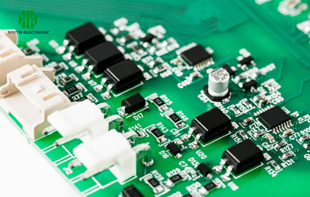
Place resistors near impedance mismatches. Calculate values using target impedance formulas. Verify with simulation tools. Route traces to avoid stubs while minimizing bends.
Step-by-Step Implementation
Follow my field-tested workflow. Start with impedance matching[^4].
Critical impedance factors:
| Factor | Importance | Calculation | Tolerance |
|---|---|---|---|
| Resistor Value | Key to absorbing energy | Zo = √(L/C) | ±1% ideal |
| Position | Distance from mismatch point | < 1/10 wavelength | Critical for HF |
| Power Rating | Prevents burnout | P = V²/R | +20% buffer |
Resistor value ties to transmission line impedance. Compute required ohms using Zo (characteristic impedance). I scope signals to fine-tune values during testing.
Location minimizes phase issues. Mount termination within inches for GHz signals. A client lost signal integrity placing resistors 5mm too far.
Power rating depends on voltage peaks. Always add a thermal safety margin. Burned resistors halted my first IoT module.
Simulate through tools like LTspice. Prototype small batches first. Measure reflections with TDR if possible.
What are alternative and advanced termination strategies beyond the resistor?
Resistors sometimes fail in extreme designs. High-frequency ghost signals still cause issues. Explore next-level approaches.
Active terminators and diode networks[^5] enhance basic resistive methods. These manage excess energy without impedance mismatches. Use them for GHz+ circuits or space-constrained boards.

Cutting-Edge Solutions
Address limits of passive termination.
Advanced strategy comparisons:
| Technique | Core Mechanism | Use Cases | Cost Impact |
|---|---|---|---|
| Active | Feedback voltage regulator | High-speed serial | High |
| Diode | Clamps voltage peaks | ESD protection | Medium |
| Capacitive | AC-coupled absorption | RF circuits | Low |
Active termination replaces resistors with a regulator. This maintains exact voltage at line ends. I use it in server motherboards to protect PCIe Gen5 signals.
Diode solutions steer reflections into power rails. This stops electrical overstress. My drone controller survived lightning strikes with Zener diodes.
Capacitive AC termination targets signal ringing. This works for RF boards like 5G transmitters. Keep capacitors under 10pF to avoid signal delays.
Hybrid designs often merge multiple methods. A medical monitor project combined diodes and active systems. This solved EMI noise issues completely.
Conclusion
Resistive termination protects signals from reflections. Choose schemes wisely, implement precisely, and upgrade methods for new challenges. Your electronics will be stable and reliable.
[^1]: Understanding resistive termination is crucial for preventing signal reflections and ensuring reliable electronic performance.
[^2]: Thevenin termination offers adjustable impedance, making it ideal for variable applications like automotive networks.
[^3]: Proper PCB layouts are critical for successful implementation of resistive termination and signal integrity.
[^4]: Learn best practices for impedance matching to enhance signal quality and reduce errors in electronic systems.
[^5]: Diode networks can protect against voltage peaks and improve reliability in sensitive electronic designs.

