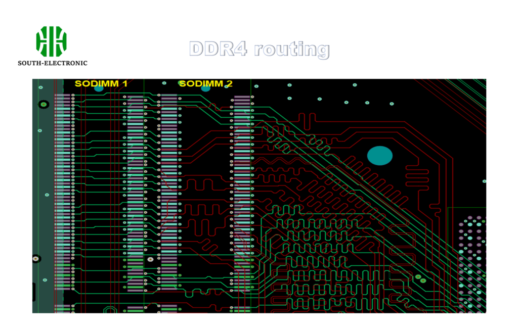
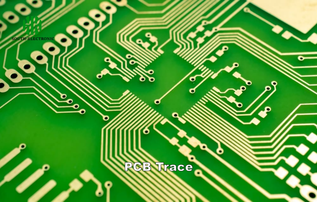
Ever struggled with timing errors in high-speed PCB designs? Signal delays can cripple performance, yet most boards aren’t flat enough for perfect synchronization. Welcome to the world of serpentine routing – where bending traces solve timing nightmares.
Snake-shaped routing intentionally adds controlled delays to faster signals, ensuring synchronized arrival times across related traces. This technique compensates for natural timing mismatches[^1] caused by varied path lengths or component placements.
For designers navigating high-speed interfaces, understanding snake routing[^2] isn’t optional – it’s survival. Let’s unravel this essential technique through four critical questions every PCB engineer should master.
What Exactly is Snake Routing & How Does It Affect Signal Delay?
Imagine two racers – one taking shortcuts, the other detours. Snake routing works like those detours. Instead of straight paths, we create intentional meanders to slow down faster signals.
Snake routing manipulates trace length to equalize signal propagation delays[^3]. Added bends increase electrical path length while maintaining logical connections, compensating for timing mismatches in parallel buses or differential pairs.
)
Three Key Factors in Delay Matching
| Parameter | Straight Trace | Snake Routing | Purpose |
|---|---|---|---|
| Physical Length | Short | Extended | Delay compensation |
| Effective Delay | Fast | Matched | Synchronization |
| Routing Freedom | Confined | Flexible | Component placement |
Three techniques dominate delay matching:
- Meander patterns: Repeated U-shaped bends
- Trombone routing: Gradual wave-like extensions
- Sawtooth routing: Angular 45-degree zigzags
Wave propagation speed in FR-4 is ≈6 in/ns. Adding 200 mils of snake routing introduces ≈33 ps delay – critical for DDR4 setups with 50 ps skew limits. Modern ECAD tools auto-calculate required meander lengths based on timing constraints.
When Are PCB Designers Forced to Use Snake-Shaped Traces?
Ever tried routing DDR4 memory without serpentine traces? It’s like conducting an orchestra without a conductor. Timing requirements demand precision no straight path can deliver.
Snake routing becomes mandatory when signal groups require matched delays[^4] beyond simple length tuning. Critical applications include clock distribution networks, parallel data buses, and differential pair phase matching.
)
Five Non-Negotiable Use Cases
| Application | Skew Tolerance | Typical Bend Style |
|---|---|---|
| DDR Memory | <50 ps | Trombone waves |
| PCIe Gen4 | 1 ps/mm | Gentle curves |
| HDMI 2.1 | 0.15 UI | Symmetric meanders |
| SONET/SDH | 0.1 UI | Cosine-shaped bends |
| ADC Clock Trees | 5 ps | Nested S-curves |
In a recent server board design, matching 16 DDR5 data lines required 3.5" of snake routing across four layers. Without it, the 6400 MT/s data rate would’ve collapsed under timing violations. High-speed protocols now demand snake routing even in space-constrained designs.
What’s the Optimal Spacing Between Parallel Snake Traces?
Cramped meanders create more problems than they solve. Crosstalk[^5] between adjacent snake traces can erase all timing benefits if spaced improperly.
Maintain at least 3× trace width spacing between parallel meanders. For 5 mil traces, use 15 mil spacing. High-speed designs (>5 GHz) require 5× spacing or ground guards between serpentine sections.
)
Spacing Rules for Different Scenarios
| Signal Speed | Minimum Spacing | Recommended Pattern |
|---|---|---|
| <1 GHz | 2× width | Trombone waves |
| 1-5 GHz | 3× width | Circular arcs |
| 5-10 GHz | 4× width | Ground-shielded S-curves |
| 10 GHz | 5× width | Coplanar waveguides |
Balancing density and isolation:
- For 100Ω differential pairs, maintain 20 mil spacing between unrelated snakes
- Add ground vias between adjacent serpentine sections in multi-GHz designs
- Use Rogers material for tighter spacing in RF applications
Failed case study: A 25Gbps SerDes design using 6 mil spacing between meanders suffered 12 dB insertion loss degradation. Increasing to 18 mil spacing restored signal integrity while meeting delay requirements.
How to Avoid Common Pitfalls in High-Speed Snake Routing?
Even experts stumble with serpentine routing – I once crippled a PCIe link by over-optimizing bend density. Timing fixes shouldn’t compromise signal integrity.
Avoid right-angle bends and symmetric patterns. Use gradual curves instead, staggering meanders across layers. Always run post-layout SI simulations with embedded S-parameter models.

Four Critical Checks for Reliable Serpentines
| Pitfall | Consequence | Prevention Method |
|---|---|---|
| Sharp corners | Impedance spikes | Use 45° or curved bends |
| No length matching | Residual skew | Measure from die to die |
| Ignoring via effects | Unmatched delays | Include via stub lengths |
| Blind simulations | Field failures | Run EM simulations at bend transitions |
Proven workflow:
- Establish maximum allowed skew (e.g., 5 ps)
- Route straight traces first
- Add meanders to shorter paths
- Simulate with worst-case process variations
- Verify with TDR/TDT measurements
A 112G PAM4 design required iterative tuning – adjusting meander amplitudes while monitoring eye diagrams. Final serpentine patterns occupied 30% of the routing area but achieved 0.8 UI eye openings.
Conclusion
Snake routing balances signal delays when precision matters most. While demanding, mastering meander patterns and spacing rules[^6] unlocks reliable high-speed designs. Remember: timing fixes must never override signal integrity[^7] – your bends should heal delays, not create new issues.
[^1]: Discover the causes of timing mismatches in PCB designs and how to address them for better synchronization.
[^2]: Explore this link to understand how snake routing can enhance your PCB designs by managing signal delays effectively.
[^3]: Learn about signal propagation delays and their impact on PCB performance to optimize your designs.
[^4]: Understanding matched delays is crucial for ensuring signal integrity in high-speed PCB designs. Explore this link to enhance your knowledge.
[^5]: Crosstalk can severely impact performance in PCB designs. Learn more about its effects and mitigation strategies to improve your designs.
[^6]: Understanding spacing rules is crucial for maintaining signal integrity in high-speed designs. Explore this resource for expert insights.
[^7]: Maintaining signal integrity is vital for reliable PCB performance. Discover effective strategies in this informative link.


