Is your electronic project failing due to overheating? Components get damaged fast without proper cooling. Choosing the wrong heatsink risks total system failure.
Select the right PCB heatsink by calculating heat output first. Then pick type and placement. Finally test performance. These steps prevent overheating and boost reliability in your devices.

Getting the heatsink choice right saves money and time. I once wasted weeks fixing heat issues. Let me show you how to avoid this.
Top or bottom for PCB heatsink placement?
Where you put heatsinks changes everything. Misplaced cooling causes unexpected hot spots.
Top placement works best for direct component contact. Bottom mounting suits space-limited boards but needs thermal vias. Always match location to heat source position for effective thermal management.
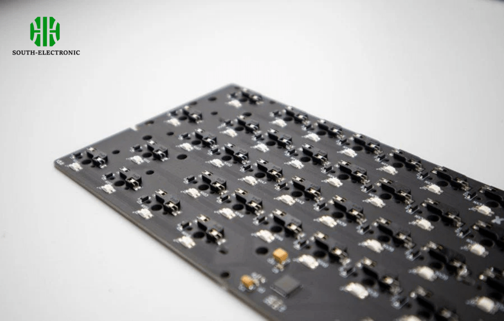
Placement depth analysis
Placement impacts heat flow directly. Let’s break this down:
Heat source access
Heatsinks must touch hot components. Top mounting does this easily. Bottom mounting requires holes or vias. These add costs.
Airflow direction
Vertical boards pull air upward. Place heatsinks in the airflow path. Horizontal boards need top-mounted heatsinks. Fans blow downward rarely.
Board space limits
Small devices force bottom placement. This adds layer complexity. Always check clearances first.
| Position Factor | Top Mount | Bottom Mount |
|---|---|---|
| Installation ease | Simple | Complex |
| Thermal resistance | Low | Medium-High |
| Space efficiency | Moderate | High |
| Component access | Direct | Via thermal vias |
Top mounting means faster heat transfer. I learned this rebuilding drone controllers. Bottom mounting helped in thin medical devices. Choose based on your device shape.
How to optimize PCB layout for better heatsink performance?
Bad layouts choke heatsink efficiency. Trapped heat kills components early.
Space heatsinks near high-power parts. Use thermal vias under chips. Increase copper areas. Keep airflow paths clear. These steps cut thermal resistance by 30-50%.

Layout enhancement methods
Optimization techniques matter most:
Copper pour strategy
Large copper planes spread heat fast. Connect them to heatsink bases. Use 2oz copper for power circuits. Thin copper increases hot spots.
Thermal via patterns
Place vias under heat sources. 0.3mm vias work best. Grid patterns beat single rows. More vias mean better cooling.
Component grouping
Cluster hot parts together. Share one big heatsink. Isolate heat-sensitive sensors. I saved a motor driver this way.
| Optimization Tactic | Impact Level | Implementation Difficulty |
|---|---|---|
| Thermal vias | High | Medium |
| Copper planes | Very High | Easy |
| Component grouping | Medium | Hard |
| Airflow channels | Medium | Medium |
Avoid blocking vents with capacitors. Measure surface temperatures after each change. My solar charger ran cooler after layout tweaks.
How to calculate heatsink needs for PCB components?
Guessing heatsink size invites failure. Overheated circuits fail suddenly.
Add power losses from all components. Use this total to find required thermal resistance. Then pick a heatsink that meets or beats that value.

Calculation step breakdown
Follow this structured approach:
Step 1: Find heat output
Record voltage and current for each part. Calculate power loss. Sum all losses. For example:
- MCU: 3.3V x 0.1A = 0.33W
- MOSFET: 1.8W
Total = 2.13W
Step 2: Check max temperatures
Each component has a max junction temperature. Allow 10°C safety margin. Ambient matters too.
Step 3: Compute required thermal resistance
Formula: (Max temp – Ambient temp) / Total Power
Room at 25°C with 60°C max? (60-25)/2.13 = 16.4°C/W needed.
Step 4: Compare heatsink specs
Pick heatsinks under 16.4°C/W here. Add thermal paste resistance (0.2°C/W).
| Calculation Phase | Key Inputs Needed | Example Value |
|---|---|---|
| Power dissipation sum | Voltage, Current per part | 2.13W total |
| Max temp allowance | Component datasheets | 60°C junction |
| Ambient temperature | Device operating environment | 25°C |
| Target thermal resistance | Result from formula | 16.4°C/W |
I once undercalculated for an LED array. It melted plastic casing. Precise math prevents accidents.
Active vs. passive PCB heatsinks: Which fits your power needs?
Choose wrong and get noise or bulk. Passive heatsinks fail silently above 10-15W loads.
Use passive heatsinks under 10W for silent running. Pick active fans (fanned heatsinks) above 10W. Active cooling handles fast heat spikes better. Noise is the tradeoff.
Selection decision guide
Compare both types:
Passive heatsink strengths
No fans mean zero noise. Simple mounting. Low maintenance needs. Good under 10W loads. Use them in audio gear and sensors. They fail above 15W without airflow.
Active heatsink advantages
Fans force air through fins. Cools 2-4X faster. Handles 15-60W without issues. Ideal for processors or power supplies. Fan failures need monitoring.
Environment considerations
Dusty places clog fan blades. Use passive in deserts. High humidity damages active fans. Go passive near water.
| Comparison Factor | Passive Heatsink | Active Heatsink |
|---|---|---|
| Cooling capacity | Low (Under 15W) | High (Up to 60W+) |
| Noise output | None | Moderate to loud |
| Cost | Low | Medium to high |
| Reliability | Very High | Medium (fan risk) |
| Maintenance | None | Fan cleaning/replacement |
My security camera used active cooling. Dust killed the fan yearly. Now I design passive when possible.
Conclusion
Choose heatsinks by calculating heat first. Optimize placement and layout. Match active/passive to your power noise needs. This keeps devices running longer.

