

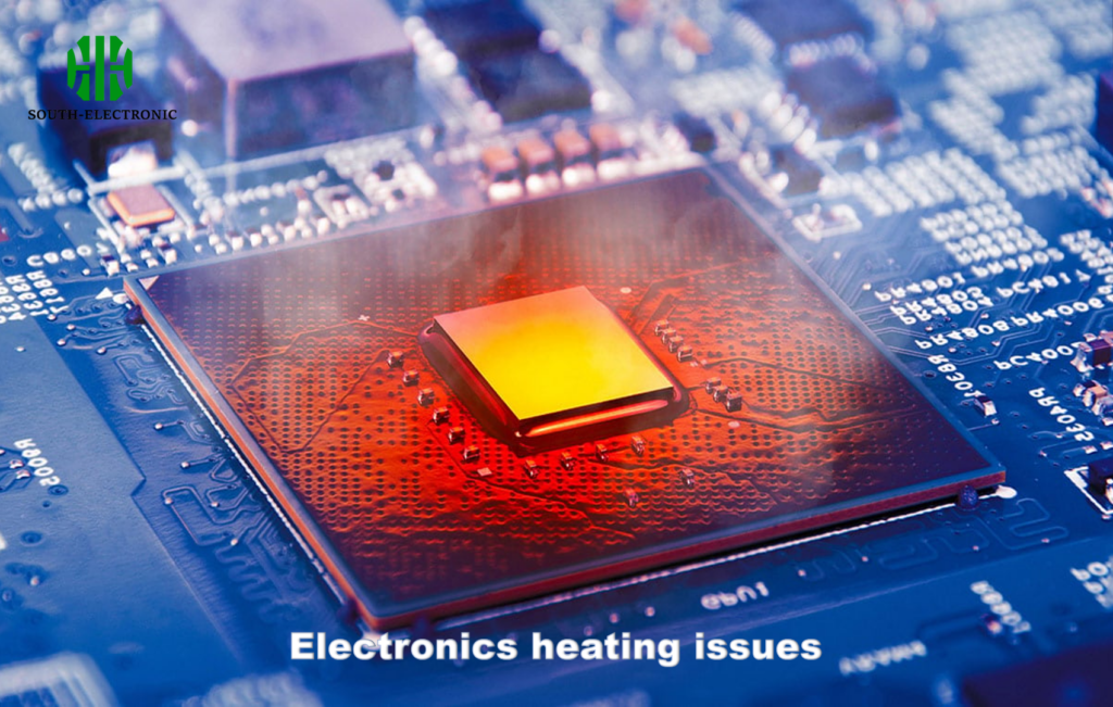
My LED installations kept failing mid-operation. The burnt smells made customers complain. Stop losing clients and money to preventable PCB fires by understanding why this happens.
LED PCBs burn out due to overheating from excessive current, poor soldering, inadequate heat dissipation, and unstable power supplies. Regular thermal checks and proper material selection can prevent 80% of these failures.

Fixing this isn’t complicated. Let me show you the exact reasons and solutions I’ve tested in my repair shop over the years.
Why Do PCBs Overheat?
Imagine finishing an expensive LED display, only to see smoke rising weeks later. Overheating sneaks up silently until it’s too late.
Excess current through components or insufficient cooling causes overheating. Voltage spikes and dense component layouts accelerate heat buildup, weakening solder joints and materials until failure occurs.
Primary Heat Sources
Several factors push PCB temperatures beyond safety limits:
| Cause | Effect on PCB | Common Failure Point |
|---|---|---|
| High-current LEDs | Localized hot spots | Solder melting around diodes |
| Poor ventilation | Trapped thermal energy | Substrate layer separation |
| Voltage fluctuations | Resistive heating in traces | Burnt copper pathways |
| Overdriven circuits | Exceeding component specifications | IC chip degradation |
Electronic components behave differently at various temperatures. For example, LED drivers generate 40% more waste heat when ambient temperatures exceed 30°C. Thin copper traces can’t dissipate heat quickly enough, creating thermal bottlenecks. Enclosed lighting fixtures worsen this by blocking airflow. I learned this the hard way when 12 aquarium LED modules failed simultaneously last summer. Preventive measures include thermal vias, heatsink integration, and derating components by 20% for high-temperature environments.
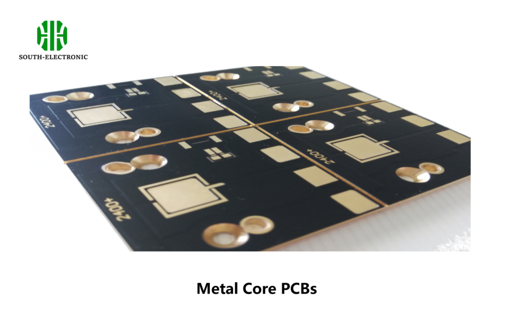
Copper vs. Aluminum Boards: Which Material Cools Better?
That client demanded refunds after copper boards warped in their warehouse lights. Material choice makes or breaks thermal performance.
Aluminum outperforms copper in heat dissipation for LED PCBs. Its 200 W/mK thermal conductivity transfers heat 40% faster than copper, preventing localized overheating in high-power applications.
Thermal Management Breakdown
Choosing between metals involves trade-offs:
| Property | Aluminum PCBs | Copper PCBs | Practical Implication |
|---|---|---|---|
| Thermal transfer | 200 W/mK | 140 W/mK | Aluminum cools hotspots faster |
| Weight | 60% lighter | Heavy | Better for ceiling/hanging lights |
| Cost | $30-$50/m² | $80-$120/m² | Aluminum reduces project budgets |
| Durability | Prone to galvanic corrosion | Oxidation-resistant | Copper wins in humid conditions |
Thermal conductivity only tells part of the story. Aluminum spreads heat uniformly, reducing thermal stress on soldered components. Copper accumulates heat around power transistors despite its conductivity. During parking lot lighting upgrades last winter, aluminum MCPCBs maintained 15°C lower temperatures than copper under identical 5A loads. However, coastal installations required copper-clad boards after saltwater corroded aluminum fins within months.
High-Tg FR4 vs. Metal-Core PCBs: Cost-Benefit Analysis for Thermal Cases
A church project went overtime when FR4 boards started charring behind stained glass. Extreme temperatures demand specialized solutions.
Metal-core PCBs handle thermal stress better than high-Tg FR4. While costing 2-3 times more, aluminum PCBs triple lifespan in high-heat scenarios like automotive or industrial lighting.
Cost vs Performance
Material selection balances budget and reliability:
| Factor | High-Tg FR4 | Metal-Core PCBs | Recommendation Threshold |
|---|---|---|---|
| Max temp handling | 150°C stable | 180°C stable | Use MCPCB above 120°C ambient |
| Production cost | $10-$25/board | $28-$70/board | FR4 suffices below 50W systems |
| Heat dissipation | Low (0.3 W/mK) | High (1-7 W/mK) | Metal-core needed for >5W LEDs |
| Repairability | Standard techniques | Specialized tools | FR4 better for prototyping |
Regular FR4 starts delaminating above 130°C glass transition temperature (Tg). High-Tg variants withstand 150°C briefly but conduct heat slowly, creating internal hotspots. Metal-core alternatives efficiently channel heat away through dielectric layers. For that museum exhibit with 7W LEDs, switching to MCPCBs eliminated $400 monthly replacement costs despite higher initial pricing. Low-wattage decorative lighting works fine with high-Tg FR4, though.
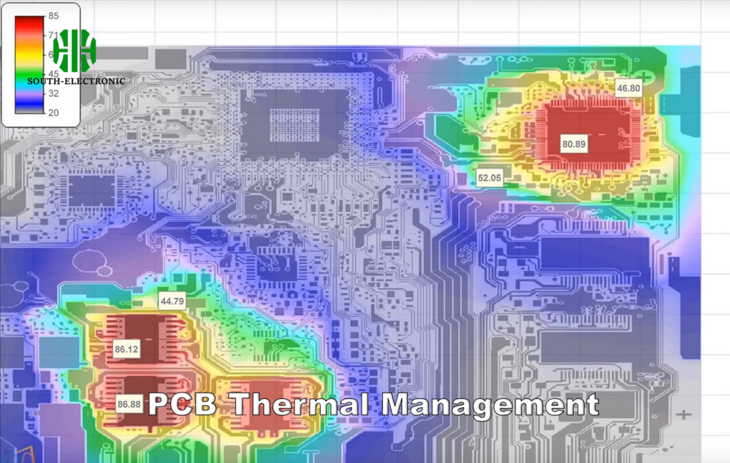
Infrared Imaging vs. Thermocouples: Which Thermal Testing Method Wins?
Mistakes in thermal validation caused three oven light replacements last quarter. Accurate testing prevents repeat failures.
Infrared cameras provide superior thermal analysis for LED PCBs. They scan entire boards instantly with ±2°C accuracy, revealing hotspots that single-point thermocouples miss during stress testing.
Diagnostic Tools Compared
Select methods based on testing needs:
| Characteristic | Infrared Imaging | Thermocouples | Best Use Case |
|---|---|---|---|
| Coverage area | Full board visualization | Single-point measurements | Detecting unknown hotspots |
| Accuracy | ±2°C | ±0.5°C | Lab-grade precision checks |
| Response time | Real-time scans | 3-5 second lag | Dynamic load testing |
| Setup complexity | Calibration required | Direct solder attachment | Quick production spot-checks |
| Testing cost | High initial equipment | Low installation | Budget-constrained environments |
Infrared captures thermal gradients across circuit traces during operation. Thermocouples physically slow heat transfer at contact points. When validating stage lights, infrared revealed 62°C spikes near connectors that thermocouples attached elsewhere missed. Thermocouples still serve well for fixed-component monitoring in cost-sensitive projects where hot zone locations are predetermined.
Conclusion
Stop LED PCB burnout by prioritizing thermal management. Use metal-core boards for high-power setups, validate temperatures with infrared, and always design cooling buffers. Reliable lighting saves repair costs.

