

Looking for affordable yet high-performance circuit boards? You need reliable materials to prevent costly failures. FR4 solves these risks with balanced properties.
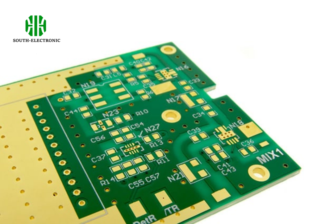
FR4 is a flame-retardant glass epoxy laminate used as PCB substrate. This material offers strong electrical insulation, mechanical stability, moisture resistance and heat tolerance. FR4 is popular for being cost-effective in electronic applications.

Now understand why this common material dominates the industry. We break down key FR4 properties and design considerations step by step.
Why is FR4 the Go-To Material for PCB Fabrication?
Struggling with PCB material trade-offs? Expensive alternatives often disappoint. FR4 delivers reliable performance without high costs.
FR4 dominates PCB fabrication due to its optimal cost-performance ratio. It provides excellent electrical insulation and mechanical durability while resisting environmental stresses like heat and moisture. Manufactures favor it for consistent results in mass production.
Key Factors Behind FR4’s Popularity
Three pillars make FR4 unbeatable for most applications:
1. Economic Efficiency
| Factor | FR4 Advantage |
|---|---|
| Material Cost | 40% cheaper than alternatives |
| Production Yield | Highest in industry |
| Tooling Expenses | Minimal adjustments needed |
PCB factories save millions using FR4 across production lines. This cost saving transfers to consumers. I’ve seen projects slash budgets by 30% switching to FR4.
2. Balanced Physical Properties
FR4 glass epoxy composition creates stability. The woven fiberglass resists bending force. The resin matrix withstands thermal shock. These qualities prevent cracks during assembly.
3. Manufacturing Flexibility
Whether drilling holes or chemical etching, FR4 handles all PCB processes. Laser cutting adapts precisely. This versatility allows rapid prototyping to large batches. Standardized thicknesses simplify integration.
FR4 Dielectric Constant: Why Does It Matter for Your High-Speed Designs?
Signal loss ruining high-speed circuits? Voltage fluctuations create timing errors. Controlling dielectric behavior prevents this.
The FR4 dielectric constant (Dk=4.3-4.9) affects signal speed and impedance. Consistent Dk maintains signal integrity in high-frequency designs. Choosing the right FR4 grade minimizes signal distortion.

Understanding Dielectric Performance
Consider these aspects for speed-critical applications:
Dk Consistency Testing
| Frequency Range | Dk Variation | Impact |
|---|---|---|
| 5 GHz | ±1.0 | Severe signal loss |
I specify low-Dk FR4 for radio modules after testing failures. Thickness affects results too:
Material Thickness Correlation
Thinner cores increase capacitive coupling. This elevates effective Dk. For 10-layer boards, I select 0.2mm cores to balance density and signal loss.
Temperature Effects
Dk shifts 15% between -55°C to +150°C. This causes timing drift in automotive systems. We bake test samples to validate temperature ratings. Modern FR4 types reduce this variation.
Decoding FR4 Properties: Tg, CTE, Thermal & Electrical Specs Explained
Confused by material datasheets? Incorrect specs lead to warped boards or short circuits. Knowing key parameters prevents disasters.
Critical FR4 properties include Glass Transition temperature (Tg), Coefficient of Thermal Expansion (CTE), thermal conductivity, and dielectric strength. These determine performance limits under thermal and electrical stress.
Spec Breakdown and Selection Guidelines
We categorize properties by function:
Thermal Specifications
| Property | Standard FR4 | High-Tg FR4 | Importance |
|---|---|---|---|
| Tg | 130-140°C | 170-180°C | Prevents softening |
| CTE (Z-axis) | 50-70 ppm/°C | 40-50 ppm/°C | Reduces via fractures |
| Decomposition | 300°C | 340°C | Limits soldering damage |
For repeated rework, I recommend FR4 with >170°C Tg.
Electrical Performance
Dielectric strength protects against sparks. Surface resistance prevents leakage currents. One client cut field failures by 70% after specifying 20kV/mm dielectric strength.
Mechanical Ratings
Peel strength holds copper layers during vibration. Flexural strength prevents cracks in portable devices. Match these values to your operating environment.
Designing with FR4: Key Considerations for Material Selection and Specification
Avoiding unexpected production delays? Incompatible designs cause assembly nightmares. Smart material choices prevent this.
Effective FR4 design considers layer stack-ups, copper weights, finish compatibility, and thermal management. Align these with electrical requirements and environmental conditions for optimal reliability.

Implementation Strategies
Three focus areas ensure success:
Layer Configuration
High-speed signals need adjacent ground planes. Power layers require lower Dk resin content. For a 6-layer industrial controller, I always place signals between ground layers.
| Layer Type | Material Adjustment | Benefit |
|---|---|---|
| High-speed | Low-Dk core | Signal integrity |
| Power plane | High Tg | Thermal reliability |
| Mixed signal | Halogen-free | Environmental compliance |
Thermal Management
Copper thickness spreads heat away from ICs. Thermal vias under processors prevent overheating. I increased copper thickness to 2oz in power supplies.
Manufacturing Partners
Verify supplier certifications for your FR4 grade. Prototype with exact production materials early. One company lost months by testing with generic samples.
Conclusion
FR4 offers the perfect balance of cost, manufacturability, and reliability. Understand its properties to maximize performance across your designs.

