
Have you noticed those tiny rectangular components on circuit boards? These unassuming parts called MLCCs make modern electronics possible. Let's explore why every designer needs to understand these microscopic powerhouses.
MLCC (Multilayer Ceramic Capacitor)[^1] is a compact capacitor made from alternating ceramic and metal layers, providing stable capacitance in minimal space. These surface-mount components handle filtering, decoupling, and energy storage in devices from smartphones to spacecraft.
While MLCCs might seem simple, their hidden complexity separates successful designs from malfunctioning ones. Let's examine five crucial aspects every engineer should know about these essential components.
What Exactly Are MLCCs and How Are They Manufactured?
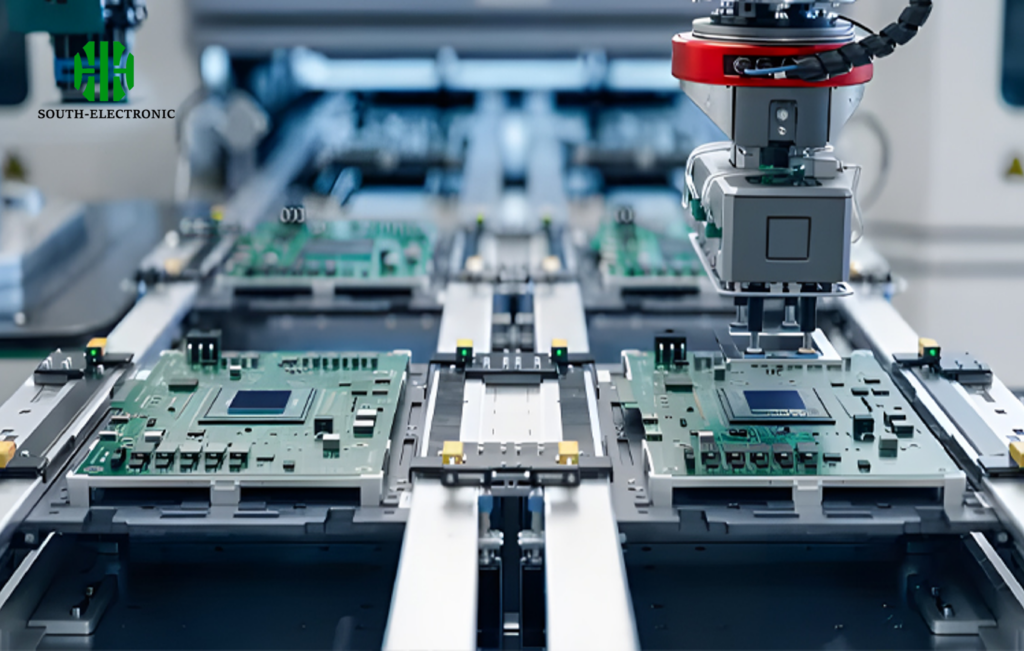
Your smartphone contains over 1,000 MLCCs - but how are these microscopic capacitors created? The manufacturing magic happens through precise layer stacking and high-temperature magic.
MLCCs are built by screen-printing metal electrode paste onto ceramic sheets[^2], stacking hundreds of layers, then firing at 1,200°C to create monolithic structures. This process enables high capacitance density[^3] in packages smaller than a grain of sand.
The Layer-by-Layer Breakdown
-
Material Preparation
Ceramic powder (BaTiO3 typically) gets mixed with binders to form flexible green sheets -
Electrode Printing
Precious metal electrodes (Pd/Ag) get deposited using screen printing -
Stacking Process
Automated machines alternate 300-1,000 ceramic/electrode layers
| Process Step | Temperature | Key Equipment |
|---|---|---|
| Sintering | 1200-1400°C | Belt furnace |
| Termination | 850°C | Plating bath |
This layered approach explains why MLCCs offer better volumetric efficiency than traditional capacitors. Military-grade MLCCs undergo 100% electrical testing to ensure ±1% tolerance.
Why Are MLCCs Critical Components in Modern Electronics?
Ever wonder why your wireless earbuds last hours on a single charge? MLCCs' unique properties enable energy-efficient designs through three key advantages.
MLCCs provide ultra-stable capacitance with minimal DC bias dependence. Their low ESR (<100mΩ)[^4] and high ripple current handling make them essential for power delivery networks in modern ICs.
)
Three Unbeatable Features
-
Miniaturization
0402 packages (0.5mm x 0.25mm) enable dense layouts -
High-Frequency Performance
Low parasitic inductance (<1nH) suits GHz-range applications -
Temperature Stability
X7R (-55°C to +125°C with ±15% ΔC)
I once debugged a drone control board failing at high altitudes. Replacing standard MLCCs with high-voltage variants solved the arcing issue - proving component selection matters.
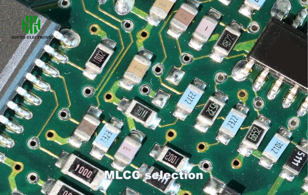
How to Choose the Right MLCC for Your Circuit Design?
Selecting MLCCs isn't just about capacitance values. The wrong choice can lead to audible noise in audio circuits or reset issues in processors.
Choose MLCCs considering three parameters: operating voltage (derate 50%), temperature characteristics (X7R vs C0G)[^5], and package size. Always verify DC bias derating curves[^6] for your application voltage.
)
Four-Step Selection Process
-
Voltage Requirements
For 5V circuits, use 10V+ rated MLCCs -
Dielectric Type
Use C0G for oscillators, X7R for decoupling -
Package Constraints
0603 for general use, 0201 for wearables
| Parameter | Decoupling | Timing Circuit | Power Filter |
|---|---|---|---|
| Recommended Type | X5R 10μF | C0G 100pF | X7R 22μF |
Avoid MLCC piezoelectric effects in MEMs sensors - I learned this when vibration caused unwanted noise in a sensor array.
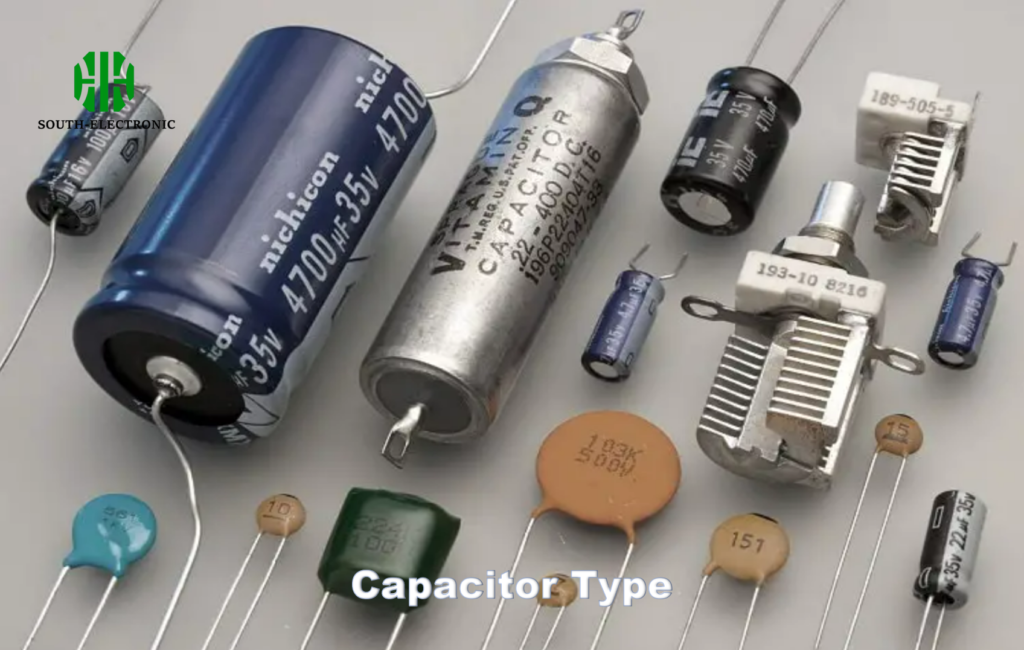
What Are the Pros and Cons of MLCCs vs. Aluminum/Tantalum Capacitors?
While MLCCs dominate modern designs, aluminum and tantalum capacitors still have their place. The choice depends on cost vs performance trade-offs.
MLCCs outperform electrolytics in ESR, lifetime, and temperature range but have lower maximum capacitance values. Tantalum offers higher CV ratio but risks thermal runaway[^7].
)
Performance Matrix Comparison
| Characteristic | MLCC | Tantalum | Aluminum |
|---|---|---|---|
| ESR | 10mΩ | 100mΩ | 500mΩ |
| Lifetime | 10+ years | 5-10 years | 2-5 years |
| Cost (10μF 16V) | $0.02 | $0.15 | $0.10 |
During component shortages, I redesigned power supplies using MLCC banks instead of tantalum. This reduced BOM cost by 40% while improving efficiency.
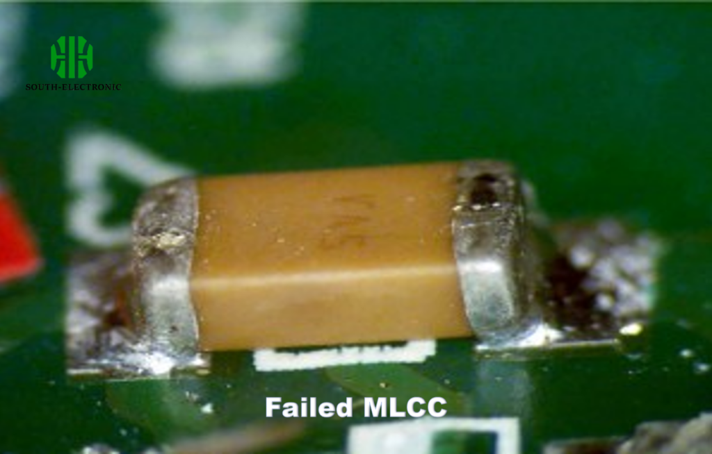
Why Do MLCCs Fail and How to Prevent Common Issues?
That mysterious circuit board failure might stem from MLCC cracks. Understanding failure modes prevents costly field returns.
MLCCs primarily fail from mechanical stress causing cracks, thermal shock during soldering, or voltage transients exceeding ratings. Proper PCB layout[^8] and derating prevent 90% of failures.
)
Five Failure Prevention Techniques
-
Avoid Board Flexure
Place MLCCs away from board edges -
Thermal Profile Control
Max 3°C/sec temperature gradient -
Use Flexible Terminations
Soft-termination MLCCs reduce crack risk -
Voltage Margin
Operate ≤50% of rated voltage -
Acoustic Noise Mitigation
For audio circuits, use anti-microphonic MLCCs
A client's IoT devices failed in cold environments. Switching from standard X7R to automotive-grade MLCCs (-55°C to +150°C) resolved the capacitance drift issue completely.
Conclusion
MLCCs enable modern electronics through miniaturized, reliable performance. Smart selection and application understanding let engineers harness their full potential while avoiding common pitfalls. Always consider operating environment and longevity requirements when implementing these essential components.
[^1]: Understanding the advantages of MLCCs can enhance your design efficiency and reliability. Explore this resource for in-depth insights.
[^2]: Learn about the materials that contribute to the performance of ceramic capacitors, crucial for effective design.
[^3]: Discover how high capacitance density can optimize your designs and improve performance in compact spaces.
[^4]: Understanding low ESR is crucial for optimizing power delivery in modern electronics, ensuring efficiency and reliability.
[^5]: Exploring temperature characteristics helps in selecting the right MLCC for specific applications, enhancing circuit reliability.
[^6]: Learning about DC bias derating curves is essential for ensuring that MLCCs perform optimally under varying voltage conditions.
[^7]: Learn about thermal runaway in tantalum capacitors to prevent potential failures in your designs and ensure reliability.
[^8]: Discover how proper PCB layout can enhance MLCC performance and prevent failures, ensuring your designs are robust and reliable.


Duncan Wiggins
Thank you for your attention to this article. You can submit your ideas at any time.
Sloane Mayer
Glad to hear from you.
We are open to any talk.