
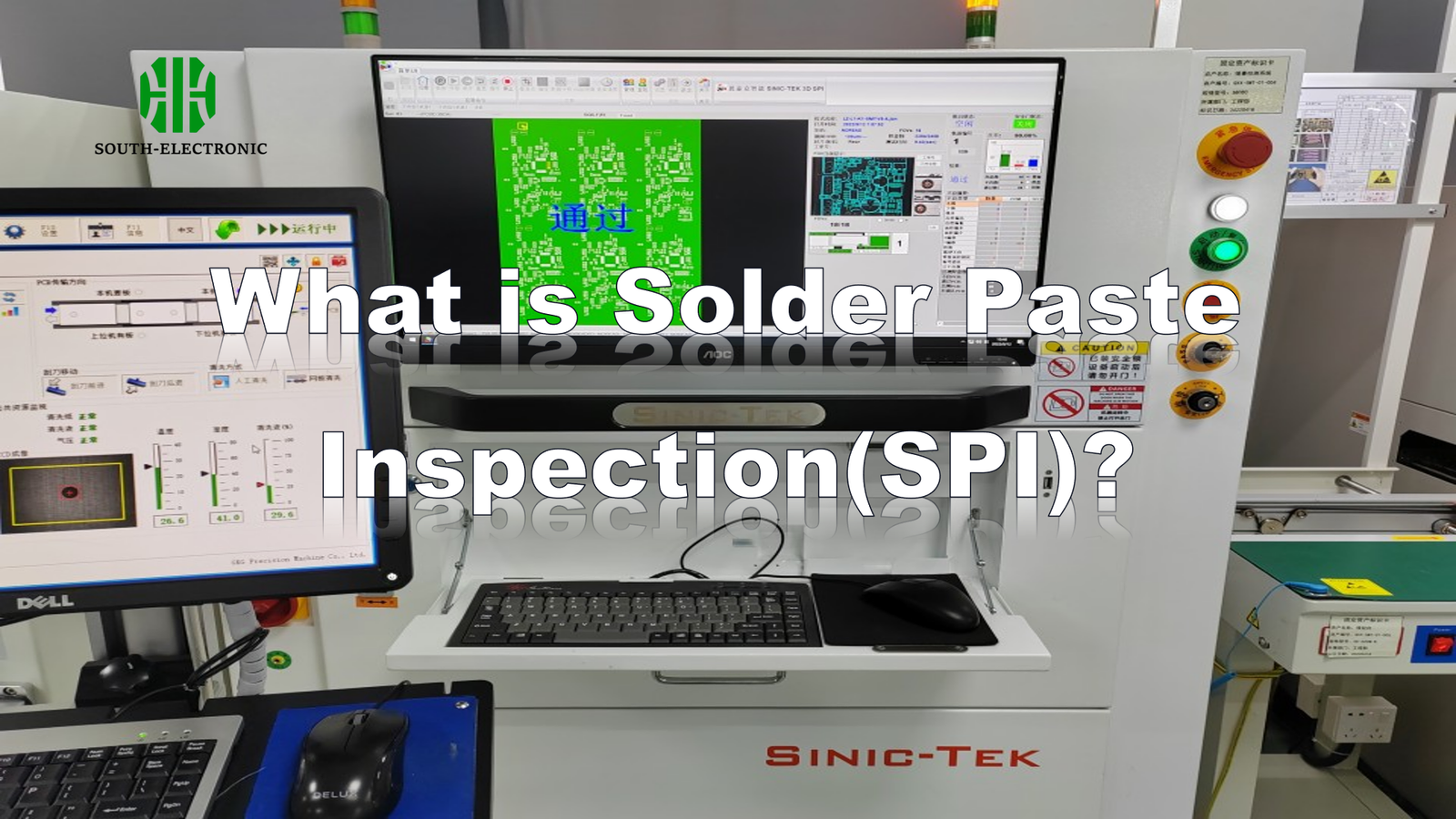
Solder defects ruin entire electronic assemblies. Discover how SPI catches these costly errors before they escalate – saving money and headaches immediately after printing.
Solder Paste Inspection (SPI) uses automated cameras to check paste on PCBs pre-reflow. It measures height, volume, and alignment accuracy. This prevents defects like shorts or weak joints by catching errors right after paste application.
Imagine stopping assembly flaws before components get soldered. I’ll explore how SPI works in practice through key technologies and setup decisions below.
What’s the real difference between 3D and 2D SPI technology?
Missing solder height issues causes late-stage failures. Understand which inspection method suits your boards before defects escape production.
2D SPI measures length/width with overhead cameras while 3D SPI uses structured lights/lasers to capture height data. 3D provides volumetric accuracy essential for modern micro-components but costs more to implement.
Core performance distinctions
These methods impact defect detection differently:
| Measurement Capability | 2D SPI | 3D SPI |
|---|---|---|
| Height Accuracy | Estimated only | Direct micron-level scans |
| Volume Calculation | Based on assumptions | Precise 3D modeling |
| Preferred Use Case | Simple PCB layouts | High-density/BGA components |
I learned the hard way that 2D SPI misses height-related defects. One time, coplanarity issues in BGA chips passed 2D checks but failed after assembly. 2D systems analyze grayscale images in two dimensions. They identify misalignment and paste spread problems well. 3D systems project patterned light and calculate height from distortion patterns. This reveals insufficient/uneven paste deposits that cause cold joints. For most manufacturers, 3D SPI is becoming essential. The volumetric data prevents reflow defects in fine-pitch components. However, 2D remains useful for simpler boards without micro-BGAs.
What do key parameters in SPI data tell you?
Ignoring SPI metrics invites assembly disasters. Learn to interpret these numbers before failed boards pile up.
Volume indicates solder sufficiency; height reveals stencil issues; area shows spreading problems; alignment confirms positional accuracy. Together they predict soldering success.
Critical measurement insights
Each SPI parameter reveals specific process issues:
| SPI Parameter | What It Measures | Production Impact |
|---|---|---|
| Volume | Total paste material deposited | Insufficient = weak joints |
| Height | Paste profile depth | Low = stencil cleaning needed |
| Area | Paste coverage percentage | Under-spread = component skipping |
| Alignment | Center offset from pad | >25% shift = placement failures |
Inconsistent volume readings once halted my production line. SPI flagged low paste deposits before placement. The height measurement revealed squeegee pressure issues. Area deviations showed stencil clogging. Alignment data exposed misregistered prints needing stencil realignment. Monitoring height variation identifies worn blades or uneven pressure. Volume trends expose paste viscosity problems. When alignment drifts beyond 25%, it causes tombstoning during reflow. Operators use these metrics to adjust printers hourly. The parameters form an early-warning system. They guide precise corrections rather than trial-error fixes.
How to choose the optimal setup between InLine and Offline SPI?
Wrong SPI integration wastes time and money. Match your solution to production reality before installing equipment.
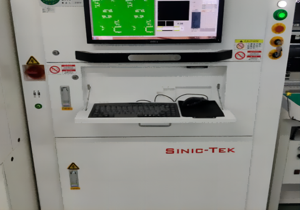
Inline SPI integrates in SMT lines for 100% inspection at line speed. Offline SPI works as separate stations for sampling checks. Choose InLine for high-volume zero-defect needs; Offline suits flexible low-volume scenarios.

Configuration decision matrix
Key factors for selection:
| Production Factor | InLine SPI | Offline SPI |
|---|---|---|
| Throughput | Handles full production | Limited by manual handling |
| Space Needed | Requires conveyor access | Standalone bench unit |
| Feedback Speed | Real-time print adjustments | Delayed analysis |
| Cost Impact | Higher upfront investment | Lower initial cost |
I prefer InLine systems for main production lines. They scan boards as conveyor moves without handling delays. Print defects trigger instant alarms. The instant feedback reduces scrap rates. Offline SPI units function well for prototypes. They work when operators manually load boards. This suits job shops with varied board sizes. Consider staffing differences: InLine needs no operator involvement. Offline SPI requires manual transfers that risk handling damage. Ultimately, volume determines your choice. Under 100 boards/hour, Offline works. Higher volumes demand integrated inspection before components advance.
Conclusion
SPI prevents soldering defects by verifying paste deposits early. Choose 3D measurement and InLine setups for optimal quality control in electronics manufacturing.

