
Microwave suddenly stops mid-cooking. Dinner plans ruined. Don’t panic yet. Understanding PCB failures prevents future headaches.
Microwave PCBs fail from overheating, signal interference, physical damage, weak manufacturing, or old parts. Better heat control, impedance tuning, robust designs, and precise assembly boost reliability significantly.
When we understand why these boards break, smart repair choices become clear. Let’s see how each component works and fails.
What is a PCB in a microwave?
That frozen pizza timer failed? Your microwave’s brain might be dying. Recognize this hidden hero before it quits.

This circuit board controls everything: power levels, timers, sensors, and magnetron firing. Think of it as the appliance’s central nervous system. Failure here cripples all functions.
Core Functions and Failure Points
Microwave PCBs serve three critical roles:
| Function | Components Involved | Common Failure Triggers |
|---|---|---|
| Power Regulation | Relays, transformers, capacitors | Overheating, voltage spikes |
| Control Processing | Microcontroller, buttons, display | Software glitches, worn contacts |
| Sensor Integration | Humidity/temp sensors, door switches | Calibration drift, dust accumulation |
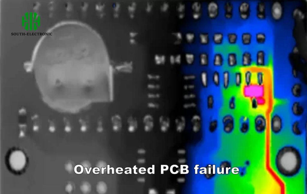
First, the power section handles dangerous high-voltage conversion. Tiny cracks in solder joints cause sudden breakdowns under heat extremes. Second, the central processor governs every command. Pressing buttons wears membrane circuits over time. Last, moisture sensors malfunction when contaminants jam detection zones.
Regular cleaning prevents board contamination. But component spacing remains crucial. Crowded parts trap heat. Good designs use thermal relief cutouts on copper layers. Airflow gaps between hot zones help. Thicker 2.oz copper traces resist burning. Precise fabrication prevents minute cracks that escalate into total failure.
Can a microwave control board be repaired?
DIY dream crushed by a blank display? Repair costs scare most owners. But total replacement isn’t always necessary.

Yes, repairs work with careful diagnostics. Swapping blown capacitors or fused relays often fixes common issues. Severe damage may require professional rework or replacement.
Repair Feasibility Analysis
I categorize repairable faults into three tiers:
1. Basic Component Replacements
- Example: Swollen capacitors near power sections
- Success Rate: 80% with proper desoldering tools
- Cost: $2-$15 per component vs. $100+ new board
Replacing surface-mount relays proves tricky without magnification. DIY enthusiasts risk pad damage. Professional shops use hot-air rework stations for clean swaps.
2. Trace Restoration
- Scenario: Charred paths from overloaded circuits
- Method: Scraping damaged coating + jumper wires
- Precision Required: Microscopic work with multimeter testing
High-current paths fail visibly. Burnt traces need copper grafting. Budget boards thinner than 1.6mm often require full replacement instead.
3. Chip-Level Failures
- Challenge: Dead microcontrollers with no drop-in substitutes
- Diagnosis: Meter signal inputs/outputs at operating voltage
- Solution: Board replacement; chip reprogramming is impractical
Assess board life through capacitor hours. Ten-year-old units may see multiple failures. Compare repair costs against appliance value first.
What are the cost vs performance tradeoffs in microwave PCB stackups?
Manufacturers use cheaper materials in budget models. Premium boards prioritize durability. Understanding this split saves long-term costs.
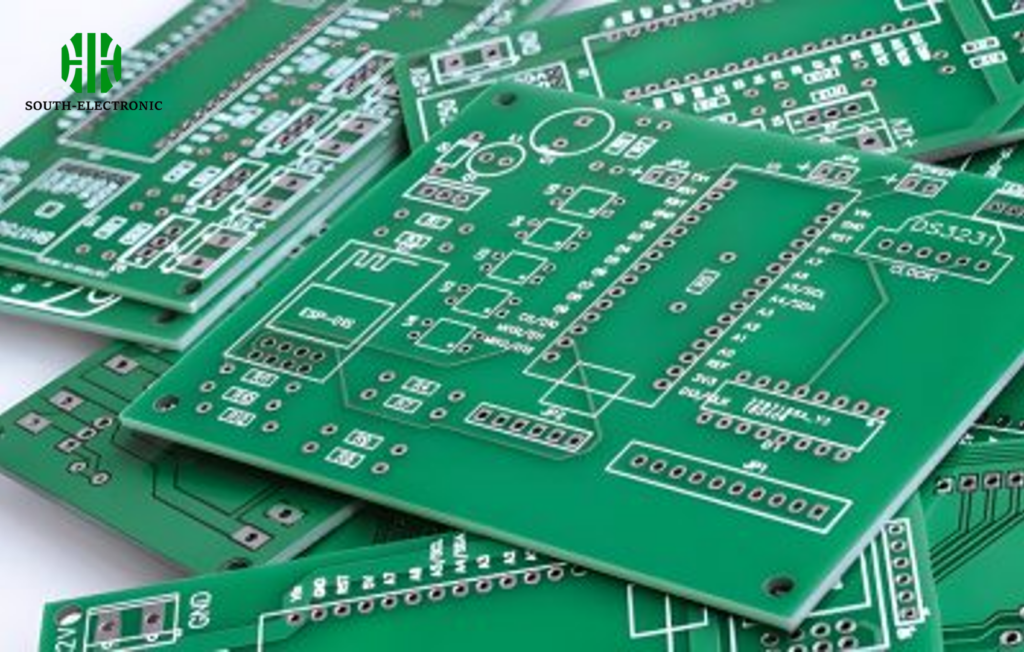
Cost-cutting reduces layers and uses basic FR-4 materials. Higher-priced stackups feature thermal-resistant substrates and robust soldering. Balance initial price against expected lifespan wisely.
Critical Microwave PCB Construction Tradeoffs
Building microwave boards involves key compromises:
| Parameter | Budget (Low Cost) | Performance (High Cost) | Reliability Impact |
|---|---|---|---|
| Base Material | Standard FR-4 | Rogers or ceramic-filled laminates | 90°C vs 200°C heat tolerance |
| Layer Count | 2 layers | 4-6 layers with ground planes | Signal noise reduction difference |
| Copper Weight | 1 oz | 2-3 oz copper traces | Current handling + heat transfer |
| Surface Finish | HASL lead-free | ENIG or immersion silver | Oxidation resistance and soldering |
| Tolerance Control | ±10% impedance | ±2% impedance matching | Minimized standing waves |
| Thermal Management | Minimal heat paths | Strategic vias + solder masks | Heat dissipation effectiveness |
Standard FR-4 works acceptably in many home microwaves. Parts rarely exceed engineers’ thermal curves. But magnetron driver circuits push boundaries. Rogers 4350B substrates better manage heat and RF stability.
Adding layers doubles material expenses. Four-layer boards with dedicated ground planes prevent signal bleed-through. Industrial units demand such setups. Costlier surface finishes like ENIG resist microwave humidity. Their microscopic gold layers protect copper from corrosion.
I prefer specifying 2oz copper for power routes. Extra thickness handles current surges without burning. It outperforms thin traces at 60% higher ampacity. Prioritize functional zones when budgeting upgrades. Optimize protection where failures occur most.
Conclusion
Microwave PCB failures come from design, use, or material flaws. Smart repairs balance costs. Choosing robust stackups extends lifespan significantly.

