
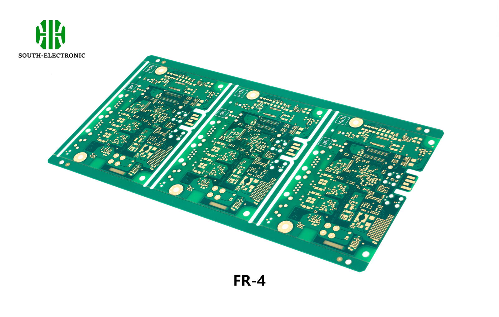
Your Trusted Supplier of FR4 PCB
South-Electronic
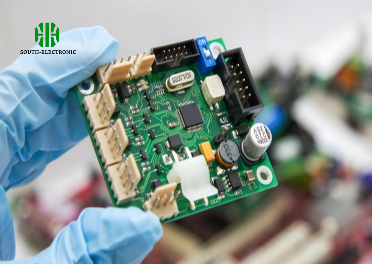
Trust South-Electronic for top-notch quality and consistency in your high-tech projects.Our FR4 PCBs enhance your devices' performance through superior electrical performance and enhanced mechanical durability.
Why Choose South-Electronic?
Choose South-Electronic for our expertise in custom, high-quality FR4 PCBs for a range of applications. Our team has extensive experience, ensuring superior quality at competitive prices and exceptional service from start to finish.
-
Quality Assurance with Extended Warranty
Your PCB projects deserve uncompromising quality, and we deliver.
Every PCB you receive from us is backed by our five-year warranty, ensuring you’re covered with free repairs for any issues that arise during this period. -
Lifetime After-Sales Support
Your peace of mind continues after the sale is complete.
With our lifetime after-sales service, you can count on ongoing support and assistance throughout the lifespan of your products, -
Flexible Ordering without MOQ
Your needs drive our flexibility.
We offer a minimum order quantity of just one piece with no upper limit, providing flexible solutions tailored to your specific demands. -
Rapid Response and Delivery
Your deadlines are important, and we meet them.
With our efficient production processes and optimized logistics, we ensure timely delivery of your orders. -
Transparent and Communicative Client Relations
Your trust in us is reinforced by transparency.
Our end-to-end supply chain visibility allows you to track your orders in real time, ensuring smoother transactions and better communication,
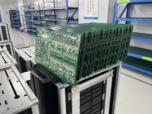
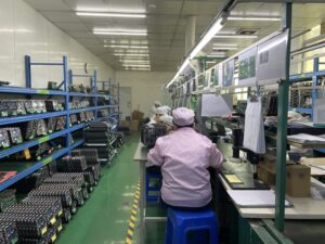
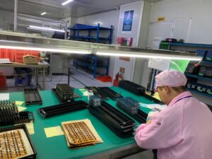
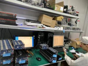
Related Project We had Done
Customer Reviews
Common Questions
Most Popular Questions
Send us a message
The more detailed you fill out, the faster we can move to the next step.


The Complete Guide For FR4 PCB
Contents
Chapter 1

Understanding FR4 Material
FR4, standing for «Flame Retardant level 4,» is one of the most commonly used materials in the fabrication of printed circuit board (PCB). This material has gained widespread acceptance due to its impressive mechanical and electrical properties which make it suitable for a wide range of electronic applications.
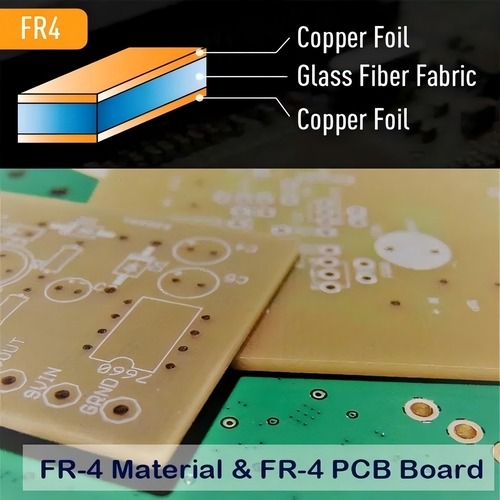
Composition of FR4
FR4 is a composite material consisting of woven fiberglass cloth with an epoxy resin binder. The fiberglass provides mechanical strength and durability, while the epoxy resin serves to bind the fibers together and gives the composite its electrical insulation properties. This composition makes FR4 an inherently flame-resistant material, hence its designation as flame retardant.
Mechanical Properties
The mechanical properties of FR4 make it highly durable under a variety of conditions. It is resistant to flexing, pressure, and environmental stresses, which makes it ideal for use in electronic devices that may experience physical impacts or need to endure harsh operational environments. The tensile strength of FR4 is typically around 45,000 psi, making it strong enough to support the weight of components soldered to the board without bending.
Electrical Properties
FR4 has excellent dielectric properties, which are crucial for preventing electrical conductivity between the circuits on a PCB. Its typical dielectric constant is around 4.5 at 1 MHz, which provides a good balance between size and performance for high-speed electronic circuits. This property is especially important in preventing signal degradation in high-frequency applications.
Thermal Properties
The thermal properties of FR4 also play a critical role in its suitability for PCB manufacturing. It has a glass transition temperature (Tg) around 130°C, which means it can withstand high temperatures during the soldering process without deforming. For applications requiring even higher thermal resistance, High-TG FR4 materials are available that can withstand temperatures up to 180°C.
Moisture Resistance
FR4 also exhibits good moisture resistance, which helps prevent corrosion of the copper circuits and maintains the integrity of the PCB throughout its operational life. This is particularly important in environments where the PCBs may be exposed to high humidity.
Availability and Cost-Effectiveness
FR4 is widely available and relatively inexpensive compared to other PCB materials, such as those used for high-frequency applications (e.g., Rogers materials). This makes it a cost-effective option for many electronic manufacturing projects, keeping production costs down while still offering good quality and reliability.
In summary, the FR4 material offers an excellent combination of strength, electrical insulation, thermal resistance, and cost-effectiveness, making it a staple in the PCB industry for everything from simple electronic devices to complex, multi-layered boards for advanced electronic applications.
Chapter 2
Benefits of Using FR4 PCB
FR4 is the backbone material for the majority of printed circuit boards (PCBs) due to its robust properties and cost-effectiveness. The utilization of FR4 offers several distinct advantages in PCB manufacturing, including excellent thermal resistance, superior electrical insulation, and significant mechanical strength. These benefits make FR4 an attractive choice for a broad spectrum of electronics applications, from consumer electronics to automotive and aerospace technologies.
1. Thermal Resistance
One of the standout attributes of FR4 is its thermal resistance. With a typical glass transition temperature (Tg) of about 130°C, standard FR4 can endure the heat generated during both the manufacturing process and normal operation without losing its structural integrity. For applications demanding even higher thermal stability, High-TG FR4 materials are available that can withstand temperatures up to 180°C or more. This makes FR4 an ideal choice for high-power and high-temperature applications, as it prevents the PCB from warping or degrading under thermal stress.
2. Electrical Insulation
FR4’s excellent electrical insulation is crucial for reliable PCB performance. This property ensures that electrical currents are confined to their intended paths, thereby preventing short circuits and electrical leaks between the layers of the PCB. The material’s dielectric constant (around 4.5 at 1 MHz) supports efficient signal propagation with minimal loss, which is essential for maintaining the integrity of electrical signals in a variety of electronic devices.
3. Mechanical Strength
The combination of woven fiberglass and an epoxy resin binder gives FR4 its notable mechanical strength, which is critical for enduring the physical and mechanical stresses that occur during product assembly, installation, and use. FR4 boards are resistant to cracking, bending, and breaking, which is particularly important for electronic devices that might be subject to impacts, vibrations, or ongoing mechanical stress.
4. Cost-Effectiveness
Compared to more specialized materials like ceramics or high-frequency materials such as Rogers, FR4 is considerably more cost-effective. This affordability makes it a preferred choice for many manufacturers, especially for standard consumer electronics where high volumes and low costs are prioritized. The widespread use and manufacture of FR4 also mean that it is readily available, helping to reduce lead times in the production of PCBs.
5. Versatility
FR4 is highly versatile and can be used in the manufacture of single-sided, double-sided, and multilayer PCBs. It can be drilled and cut into various shapes and sizes, which allows for a wide range of applications. Furthermore, FR4 is compatible with various surface finishes and can support numerous types of electronic components, from simple capacitors and resistors to complex integrated circuits.
6. Chemical and Moisture Resistance
FR4 shows good resistance to many chemicals, including solvents and cleaning agents used in the assembly and maintenance of electronic devices. Additionally, its moisture resistance helps in preventing corrosion and other moisture-related deterioration over time. This is crucial for maintaining the longevity and reliability of the PCB, particularly in humid or volatile environments.
7. Flame Retardancy
As implied by its name (Flame Retardant 4), FR4 is inherently flame retardant. This characteristic is vital for safety in electronic applications, reducing the risk of fire and damage in case of circuit overloads or failures.
In conclusion, FR4 PCBs offer a balanced mix of performance, durability, and cost, making them a foundational element in the electronics manufacturing industry. Whether for everyday consumer gadgets or more demanding industrial applications, FR4 provides the reliability and functionality required to meet the diverse needs of modern electronics.
Chapter 3
Types of FR4 PCBs
1. Standard FR4 PCBs
Standard FR4 PCBs are the most commonly used in the electronics industry. They provide a good balance of mechanical, thermal, and electrical properties at a cost-effective price point. Standard FR4 has a glass transition temperature (Tg) of about 130°C, which is sufficient for many consumer electronics and typical industrial applications. It offers excellent dimensional stability, which is crucial for multi-layer PCBs where alignment between the layers is critical. This type of FR4 is widely favored for its reliability in standard applications and its ability to perform well in most environmental conditions.
2. High-TG FR4 PCBs
High-TG FR4 PCBs are made from a type of FR4 that has a higher glass transition temperature than the standard variant. The Tg of these materials typically ranges from 170°C to 180°C, making them more suitable for high-temperature applications. High-TG FR4 is ideal for environments where the PCB is expected to experience elevated temperatures that would exceed the capabilities of Standard FR4, such as in automotive engine components, high-density power supplies, or lighting applications involving high-power LEDs. The increased thermal stability helps prevent delamination, warping, and other mechanical degradations under heat stress.
3. Halogen-Free FR4 PCBs
Halogen-Free FR4 PCBs are designed to be more environmentally friendly and safer in terms of fire hazard management. Standard FR4 uses tetrabromobisphenol-A (TBBPA) as a flame retardant, which contains bromine, a halogen that can release toxic and corrosive gases when burned. Halogen-free FR4 substitutes these traditional halogenated flame retardants with non-halogenated alternatives, reducing the emission of toxic gases during combustion or in the event of a fire. This type of PCB is particularly important in applications where environmental and health regulations require reduced halogen content, such as in home appliances and consumer electronics marketed in environmentally conscious markets.
4. Flex-Rigid FR4 PCBs
Flex-Rigid FR4 PCBs combine flexible and rigid board technologies using FR4 material for the rigid sections and flexible high-performance polymers for the flex parts. This type allows for a more complex and compact design, providing excellent electrical performance and higher resistance to vibrations and bending stresses. They are typically used in sophisticated electronic devices where space is limited and multiple connections between different sections of the device are necessary, such as in cameras, mobile phones, and wearable technology.
5. Lead-Free Compatible FR4 PCBs
With the increasing global emphasis on reducing lead use in electronics, Lead-Free Compatible FR4 PCBs have been developed to withstand the higher temperatures required by lead-free soldering. This variant of FR4 ensures that the PCB can endure the approximately 260°C temperature typically involved in lead-free soldering processes without degradation, thereby complying with RoHS (Restriction of Hazardous Substances) standards.
Each type of FR4 PCB serves distinct industry needs and regulatory requirements, allowing engineers and designers to select the most appropriate material based on the specific operational demands and environmental conditions their electronic products will face. This diversity ensures that FR4 remains the material of choice across a broad spectrum of electronic manufacturing applications.
Chapter 4
Applications of FR4 PCBs
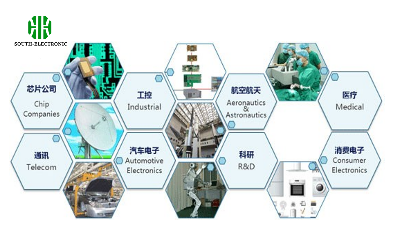
FR4 PCBs are integral to the electronics industry, serving as the backbone for a multitude of devices across a wide range of sectors. The versatility and robust characteristics of FR4 make it ideal for applications from basic consumer electronics to critical aerospace and automotive systems. Below is a detailed look at how FR4 PCBs are applied in various industries:
1. Consumer Electronics
FR4 is predominantly used in consumer electronics due to its reliability, cost-effectiveness, and excellent electrical insulation properties. Common devices that incorporate FR4 PCBs include smartphones, computers, televisions, home appliances, and personal gadgets. In these applications, FR4 provides the necessary durability and performance stability that consumer products require, ensuring that devices operate efficiently under typical usage conditions.
2. Automotive Industry
In the automotive sector, FR4 PCBs are essential in both standard and advanced applications, from control systems and LED lighting to infotainment systems and safety sensors. Vehicles demand electronics that can withstand vibrations, fluctuations in temperature, and long-term wear and tear. High-TG FR4 PCBs are particularly valuable in this industry due to their enhanced thermal stability, which is crucial for under-the-hood applications where temperatures can be high.
3. Aerospace and Aviation
Aerospace applications impose stringent requirements on PCB materials, including extreme temperature resistance and high reliability under stress. FR4 PCBs are used in a variety of aerospace components such as communication systems, instrumentation, satellites, and control tower systems to ensure consistent performance and durability. While more specialized materials may also be used, FR4 finds its place in less critical components where its properties are sufficient to meet the demands of aerospace environments.
4. Industrial Electronics
FR4 PCBs are widely used in industrial electronics for control systems, power distribution boards, and monitoring devices. Industrial environments often expose electronics to harsh conditions, including corrosive substances, excessive dust, and significant temperature variations. FR4’s mechanical strength and thermal stability make it suitable for such applications, providing a reliable base for heavy-duty industrial electronic components.
5. Medical Devices
In the medical field, FR4 PCBs are used in non-implantable medical devices such as monitors, imaging equipment, and diagnostic instruments. These applications benefit from FR4’s dependable insulation properties and its ability to support complex, multi-layered PCB designs which are often required in sophisticated medical devices.
6. Telecommunications
The telecommunications industry utilizes FR4 PCBs in infrastructure such as routers, switches, and base stations. These devices require materials that can support high-speed signal transmission and withstand the environmental conditions of various installation sites, making FR4 an excellent choice due to its effective electrical performance and durability.
7. Lighting Technology
With the growth of LED technology, FR4 PCBs have become increasingly popular in lighting applications. FR4 is used to manufacture LED PCBs which not only support LEDs structurally but also help in heat dissipation, essential for maintaining the efficiency and lifespan of LED lights.
8. Renewable Energy Systems
FR4 PCBs find applications in renewable energy systems, including solar inverters and wind turbine controllers. These systems require robust electronics capable of enduring environmental stresses and FR4 provides a cost-effective solution with sufficient durability and performance.
Conclusion
The wide-ranging applications of FR4 PCBs underscore their fundamental role in modern electronics. From everyday gadgets to sophisticated industrial and aerospace systems, FR4’s combination of affordability, reliability, and versatility makes it an indispensable material in the electronics manufacturing landscape.
Chapter 5

Manufacturing Process of FR4 PCBs
The manufacturing of FR4 printed circuit boards (PCBs) is a detailed process involving several critical steps. Each phase of production must be meticulously managed to ensure that the final product meets the required specifications and performance standards. Here’s a comprehensive step-by-step guide on how FR4 PCBs are manufactured:
1. Design and Layout
The process begins with the PCB design, typically done using specialized software like CAD (Computer-Aided Design) tools. Designers lay out the circuit schematic and then translate this into a physical board layout, which dictates where components will be placed and where tracks will connect them. The layout must consider factors such as space constraints, the electrical requirements of the circuit, and the thermal management needs.
2. Material Selection
Once the design is finalized, the appropriate FR4 material is selected based on the requirements of the project. Factors influencing this choice include the operating temperature range, the mechanical strength needed, and the budget constraints of the project.
3. Cutting and Preparing the FR4
The FR4 sheets are then cut to the required size using a precision saw. This step must be handled carefully to prevent the edges from fraying, which can affect the quality of the finished PCB.
4. Drilling
Holes are drilled into the cut FR4 sheets to accommodate mounted components and vias, which are electrical connections between different layers of the PCB. This is typically done with automated drilling machines that can handle the fine precision required for the small holes.
5. Circuit Pattern Printing
The next step involves transferring the circuit patterns onto the FR4 boards. This is often done using a photolithographic process where a photoresist is applied to the board, exposed to light through a mask shaped according to the circuit layout, and then developed to remove the unexposed photoresist. The exposed areas are then chemically etched away to leave copper tracks that form the circuit pattern.
6. Layer Stacking and Lamination
For multilayer FR4 PCBs, individual layers must be aligned and then laminated together. Pressure and heat are applied to bond the layers together using an adhesive material that also acts as an insulating layer. This step is critical for the integrity and functionality of multilayer PCBs.
7. Plating and Copper Deposition
After lamination, the PCB undergoes a plating process to add copper to the drilled holes, which forms the vias. This step ensures that electrical connectivity is maintained across the different layers of the PCB.
8. Solder Mask Application
A solder mask is then applied over the entire PCB surface except where soldering will take place (i.e., the pads). This layer protects the copper circuits from oxidation and prevents solder bridges between closely spaced solder lands.
9. Silkscreen Printing
Component identifiers and other markings are printed on the PCB using a silkscreen process. This helps in assembling the PCB, as it indicates where each component should be placed.
10. Surface Finish
A surface finish is applied to the copper pads to protect them from oxidation and improve solderability. Common finishes include HASL (Hot Air Solder Leveling), ENIG (Electroless Nickel Immersion Gold), and OSP (Organic Solderability Preservatives).
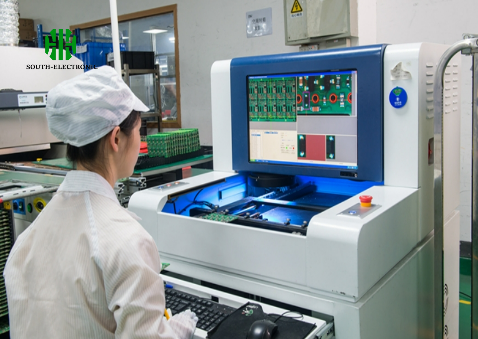
11. Testing and Quality Assurance
The final stage involves rigorous testing to ensure that the PCB meets all design specifications and is free from defects. Testing methods can include visual inspection, automated optical inspection (AOI), in-circuit testing (ICT), and functional testing.
12. Packaging and Shipping
Once tested and approved, the PCBs are packaged securely to prevent damage during shipping and then dispatched to the customer.
This manufacturing process ensures that FR4 PCBs are produced to high standards, suitable for a wide range of applications from simple devices to complex, critical systems.
Chapter 6
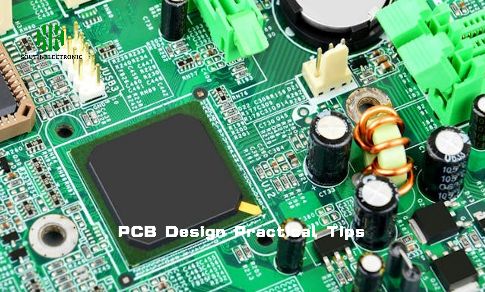
Design Considerations for FR4 PCBs
Designing printed circuit boards (PCBs) using FR4 material requires careful consideration of several key factors to ensure optimal performance and manufacturability. Here’s a detailed examination of the critical design elements that should be taken into account when creating FR4 PCBs.
1. Layer Count
The layer count of a PCB refers to the number of individual layers of copper tracks and insulating material in the board. The choice of how many layers to use depends on the complexity of the circuitry and the electrical requirements of the device. More layers allow for more complex routing and better electromagnetic compatibility (EMC) performance but increase the cost and complexity of manufacturing. For simple devices, a single-sided or double-sided PCB might suffice, whereas more complex electronic systems, such as computer motherboards or communication equipment, may require multi-layer PCBs (four layers, six layers, or more).
2. Board Thickness
The thickness of the PCB affects both the mechanical stability of the board and its thermal and electrical properties. Standard FR4 PCBs typically range from 0.8 mm to 1.6 mm in thickness, but thicker or thinner boards can be used based on specific needs. Thicker boards are more robust and better at dissipating heat but are also heavier and more expensive. The choice of thickness often needs to balance mechanical strength against weight and cost considerations, especially in portable electronic devices.
3. Trace Width and Spacing
Trace width is critical in PCB design as it determines the current-carrying capacity of the copper tracks. Wider traces can carry more current and are less prone to heat buildup but take up more space on the board, which may be at a premium. Trace spacing, the distance between adjacent copper tracks, is equally important as it affects the likelihood of electrical short-circuits between traces and impacts signal integrity. Designers must adhere to minimum spacing guidelines, which vary depending on voltage levels and manufacturing capabilities.
4. Copper Weight
Copper weight refers to the thickness of the copper foil that forms the traces and planes on the PCB. It is usually expressed in ounces per square foot and typical values are 1 oz, 2 oz, or more. Higher copper weights allow for greater current carrying capacity and better thermal management but can make etching finer features more challenging.
5. Via Types
Vias are small holes in a PCB that are filled or plated with copper to make electrical connections between different layers. The type of vias used can significantly affect the performance and cost of a PCB. Through-hole vias pass through the entire board and are easy to implement but consume valuable space. Blind vias connect the outer layer to one or more inner layers without going through the entire board, and buried vias connect internal layers without reaching the outer surfaces, both of which help save space and improve performance in multi-layer boards.
6. Thermal Management
Effective thermal management is crucial in PCB design to ensure reliable operation and prevent overheating. FR4 has good thermal insulation properties, but designers may need to incorporate heat sinks, thermal vias, and carefully plan the layout to ensure heat is adequately dissipated, especially in high-power applications.
7. Component Placement
Strategic placement of components is vital for minimizing signal path lengths and reducing electromagnetic interference (EMI). Components should be arranged to optimize routing efficiency, with sensitive components placed away from potential sources of interference.
8. Signal Integrity
For high-speed applications, maintaining signal integrity is crucial. Factors such as trace geometry, board layout, and the use of differential pairs and impedance control must be carefully considered to minimize signal degradation over distance and through connectors.
9. Manufacturing Tolerances
Designers must also consider the manufacturing tolerances of the PCB fabrication process. This includes allowances for variations in line widths, spacing, and hole sizes, which can affect the final performance of the PCB.
10. Regulatory Compliance
Finally, designers must ensure that the PCB design complies with applicable standards and regulations, such as those related to electromagnetic compatibility (EMC), RoHS (Restriction of Hazardous Substances), and UL (Underwriters Laboratories) certification.
These design considerations are integral to creating functional and reliable FR4 PCBs that meet the required specifications and are manufacturable at scale. Each aspect requires careful analysis and optimization to achieve the best possible outcome for the intended application.
Chapter 7

Challenges and Solutions in FR4 PCB Usage
While FR4 is widely used and provides a balance of cost, performance, and manufacturability, it is not without its challenges, particularly in advanced electronic applications. Here are some of the most common challenges faced when using FR4 PCBs and practical solutions to address these issues.
1. Heat Management
Challenge: FR4 has limited thermal conductivity, which can pose challenges in heat-sensitive applications. Excessive heat can lead to delamination, performance degradation, and even failure of the PCB.
Solutions:
- Use of High-TG FR4: Employing High-TG FR4 materials can help as they withstand higher temperatures before degrading.
- Thermal Vias: Implementing thermal vias can effectively transport heat from the top to the bottom layer of the PCB, where it can be dissipated more efficiently.
- Heat Sinks: Attaching heat sinks directly to heat-generating components or to the PCB itself can help dissipate heat.
- Proper Component Layout: Designing the layout to spread heat-producing components evenly across the board can prevent hot spots.
2. Signal Integrity
Challenge: FR4’s dielectric properties can lead to signal degradation, especially at higher frequencies. This is due to the material’s relatively high dielectric constant and loss tangent.
Solutions:
- Controlled Impedance Design: Using controlled impedance design techniques helps maintain signal integrity across the PCB.
- Material Selection: For high-frequency applications, consider using materials with lower dielectric constants and loss tangents than standard FR4, such as RF-specific laminates.
- Stackup and Routing Optimization: Optimizing the PCB stackup and routing can minimize signal loss and cross-talk, particularly important in high-speed designs.
3. Dimensional Stability
Challenge: FR4 can exhibit dimensional instability due to changes in moisture absorption and thermal expansion, which can complicate the assembly process, particularly for fine-pitch components.
Solutions:
- Bake-Out Process: Prebaking the PCBs before assembly can drive out moisture and reduce the risk of dimensional changes during soldering.
- Use of Fillers: Using FR4 materials that include fillers can improve dimensional stability by reducing the coefficient of thermal expansion (CTE).
4. Chemical and Moisture Resistance
Challenge: FR4 is susceptible to moisture absorption, which can affect its dielectric properties and lead to potential delamination and other moisture-related failures.
Solutions:
- Protective Coatings: Applying conformal coatings can protect PCBs from moisture and chemical exposure.
- Enclosures: Using robust enclosures can also shield the boards from harsh environmental conditions.
5. Environmental Concerns
Challenge: Standard FR4 uses tetrabromobisphenol-A (TBBPA) for flame retardancy, which can release toxic brominated compounds when burned.
Solutions:
- Halogen-Free FR4: Switching to halogen-free FR4 materials can mitigate environmental and health risks by avoiding brominated flame retardants.
6. Manufacturing Precision
Challenge: The precision required for placing and soldering components on high-density FR4 PCBs can be difficult to achieve, especially as component sizes decrease and density increases.
Solutions:
- Advanced Manufacturing Techniques: Employing state-of-the-art manufacturing techniques such as laser drilling and direct imaging can enhance the precision of PCB features.
- Design for Manufacturability (DFM): Early collaboration between the PCB designers and manufacturers can ensure that the design adheres to manufacturability principles, reducing the risk of errors.
By addressing these challenges with targeted solutions, the usability and reliability of FR4 PCBs can be significantly enhanced, making them suitable for a wider range of applications while maximizing their inherent advantages.
Chapter 8
Comparing FR4 PCBs with Other PCB Materials
FR4 is one of the most widely used materials for printed circuit boards (PCBs), but there are other materials like CEM1, CEM3, and various Rogers materials that also find significant use in specific applications. Understanding the differences in performance and cost implications between these materials can help designers choose the right material for their needs. Here’s a detailed comparative analysis of FR4 with these other PCB materials.
FR4 vs. CEM1 and CEM3
Composition:
- FR4: Composed of woven fiberglass and epoxy, FR4 is known for its durability, flame resistance, and good electrical insulation properties.
- CEM1 and CEM3: Both are composite epoxy materials. CEM1 is a paper-based laminate with one side glass epoxy and is less durable than FR4. CEM3 is similar to FR4 but uses a combination of woven glass and paper, often considered a blend between FR4 and CEM1.
Performance:
- Thermal and Mechanical Stability: FR4 generally provides better thermal and mechanical stability than CEM1 but is comparable to CEM3. FR4’s higher glass transition temperature makes it suitable for applications involving higher temperatures.
- Electrical Properties: FR4 offers superior electrical insulation compared to CEM1 and is on par with CEM3. This makes FR4 a better choice for high-frequency applications than CEM1.
Cost:
- CEM1 is typically cheaper than both FR4 and CEM3, making it a cost-effective option for single-sided PCBs where less durability is acceptable.
- CEM3 is generally less expensive than FR4 but more costly than CEM1. It strikes a balance between cost and performance, making it suitable for applications that require better performance than CEM1 but where cost is still a concern.
FR4 vs. Rogers Materials
Composition:
- FR4: As noted, FR4 is a fiberglass and epoxy composite.
- Rogers Materials: These are high-performance PCB materials that use ceramic bases to provide enhanced electrical properties. They are designed specifically for high-frequency applications.
Performance:
- Frequency Handling: Rogers materials are superior to FR4 when it comes to handling high frequencies. They have lower dielectric losses, making them ideal for microwave and RF applications.
- Thermal Conductivity: Rogers materials also typically exhibit better thermal conductivity than FR4, which can be crucial for heat management in power-intensive applications.
Cost:
- Rogers materials are significantly more expensive than FR4. The cost can be justified by the need for high performance in advanced electronic applications where typical FR4 materials would not suffice.
Cost Implications and Application Suitability
- FR4: Most cost-effective for general electronics, including consumer and commercial products where high frequency and high thermal conductivity are not critical.
- CEM1 and CEM3: Suitable for less demanding applications where cost is a significant factor. CEM3 can be used in some multilayer designs due to its improved properties over CEM1.
- Rogers Materials: Best suited for high-frequency and high-thermal applications such as in aerospace, military, and telecommunications equipment where performance cannot be compromised.
Conclusion
Choosing the right PCB material depends largely on the specific requirements of the application, including mechanical, thermal, and electrical performance needs, as well as cost considerations. While FR4 is sufficient for a wide range of applications, certain scenarios require the unique properties offered by materials like CEM1, CEM3, or Rogers, each bringing its own set of advantages and disadvantages to the table.
Chapter 9
Future Trends in FR4 PCB Technology
FR4 has been a cornerstone material in PCB manufacturing for decades due to its robust performance and cost-effectiveness. However, as technology progresses and demands evolve, the future of FR4 PCB technology is poised to see several innovative developments aimed at addressing emerging challenges and enhancing capabilities. Here are some key trends and innovations that are likely to shape the future of FR4 PCB technology:
1. Enhanced FR4 Materials
- High-Performance Variants: The development of high-performance FR4 variants with improved thermal and electrical properties is ongoing. These materials will cater to the increasing demands of power density and thermal management in compact electronic devices. Enhanced FR4 materials will likely feature higher glass transition temperatures, improved dimensional stability, and reduced moisture absorption.
- Eco-Friendly FR4: With growing environmental concerns and regulatory pressures, there is a trend toward developing more sustainable and less harmful FR4 variants. This includes the reduction or elimination of halogens, which are known to release toxic gases when burned. Eco-friendly FR4 materials will not only help manufacturers meet stricter environmental regulations but also appeal to consumers who prioritize sustainability.
2. Integration with Advanced Manufacturing Technologies
- Additive Manufacturing: The integration of FR4 with 3D printing technologies is an exciting development. This approach allows for the additive manufacturing of PCBs, where material is deposited only where needed, reducing waste and potentially enabling more complex geometries and multi-material integration within a single PCB.
- Direct Digital Manufacturing (DDM): This technology involves the direct fabrication of PCBs from digital designs using advanced manufacturing techniques. It offers the potential for rapid prototyping and on-demand production of FR4 PCBs, significantly reducing lead times and costs associated with traditional manufacturing processes.
3. Improved Design Software and Tools
- Advanced Simulation Tools: Enhanced design and simulation tools are being developed to work more seamlessly with FR4 materials, allowing designers to more accurately predict the behavior of their circuits under various physical and environmental conditions. This includes better models for thermal management, signal integrity, and mechanical stress.
- Integrated Design Environments: Software developers are working on more integrated PCB design platforms that can handle everything from schematic capture to layout and simulation, all optimized for the latest FR4 materials. These tools aim to improve design efficiency and accuracy, reducing the time to market.
4. Multifunctional FR4 PCBs
- Embedded Components: There is a trend towards embedding passive components directly into the FR4 substrate, which can help reduce PCB size and improve performance by minimizing interconnect lengths. This technology will likely expand to include more active components and even microelectromechanical systems (MEMS) in the future.
- Smart FR4 PCBs: Integrating sensors and IoT capabilities directly into FR4 PCBs could transform them from passive circuit carriers into active, smart components of an electronic system. This could include temperature sensors, strain gauges, or wireless communication modules, opening up new applications in monitoring, diagnostics, and connectivity.
5. Global Supply Chain Innovations
- Localized Production: As geopolitical and economic factors influence global supply chains, there may be a shift towards more localized or regional production of FR4 PCBs. This could involve setting up smaller, more flexible manufacturing units closer to end users to reduce dependencies and improve supply chain resilience.
Conclusion
The future of FR4 PCB technology is shaped by a blend of material innovations, advanced manufacturing processes, and new design tools. These developments are not only expected to enhance the performance and sustainability of FR4 PCBs but also open up new applications and markets, further solidifying their role in the electronics industry. As these technologies mature, they will continue to drive the evolution of electronic products, making them more efficient, capable, and responsive to the needs of a rapidly changing technological landscape.
Chapter 10
Conclusion
Throughout this detailed exploration of FR4 PCB technology, we’ve uncovered the fundamental aspects that make FR4 a preferred material in the electronics manufacturing industry, as well as the challenges and opportunities it presents. As we look to the future, the role of FR4 in electronics is set to evolve, adapting to new demands and innovations. Here are the key points discussed and final thoughts on the future trajectory of FR4 PCBs.
Key Points Discussed:
Versatile Material Properties: FR4’s widespread use is primarily due to its excellent balance of electrical insulation, thermal resistance, and mechanical strength, making it suitable for a broad range of applications, from consumer electronics to more demanding environments like automotive and aerospace.
Challenges and Solutions: While FR4 serves many applications well, it faces challenges such as limited thermal conductivity and issues with signal integrity at higher frequencies. Innovations in material science and PCB design are continuously evolving to address these challenges, enhancing the performance of FR4 PCBs through the development of high-TG and halogen-free variants, among other advancements.
Manufacturing and Design Innovations: The integration of advanced manufacturing technologies such as additive manufacturing and direct digital manufacturing with FR4 PCB production is revolutionizing how these boards are produced, offering greater flexibility and faster turnaround times.
Future Trends: Looking ahead, the development of enhanced FR4 materials that offer better performance and environmental sustainability is critical. The future will likely see FR4 becoming smarter with the integration of functionalities such as embedded sensors and IoT capabilities.
Final Thoughts:
As electronics continue to pervade every aspect of modern life, the demands on PCB materials like FR4 grow more complex. The evolution of FR4 is not just about enhancing its physical properties but also about integrating it more deeply with technological trends such as miniaturization, wearables, and IoT devices. The drive towards more sustainable manufacturing practices and the need for more resilient global supply chains will also shape the future development of FR4 PCB technologies.
In conclusion, FR4 PCBs are expected to retain a significant role in electronic manufacturing, driven by both innovation within the material itself and its integration with new manufacturing processes. As designers and engineers continue to push the boundaries of what’s possible with FR4, we can anticipate more sophisticated and high-performing electronics that leverage the inherent strengths of this versatile material. The journey of FR4 in electronics manufacturing is far from over; it is evolving, adapting, and expanding to meet the needs of tomorrow’s technology today.
Get in touch
Where Are We?
Industrial Park, No. 438 Donghuan Road, No. 438, Shajing Donghuan Road, Bao'an District, Shenzhen, Guangdong, China
Floor 4, Zhihui Creative Building, No.2005 Xihuan Road, Shajing, Baoan District, Shenzhen, China
ROOM A1-13,FLOOR 3,YEE LIM INDUSTRIAL CENTRE 2-28 KWAI LOK STREET, KWAI CHUNG HK
service@southelectronicpcb.com
Phone : +86 400 878 3488
Send us a message
The more detailed you fill out, the faster we can move to the next step.

