
Услуга проектирования гибких печатных плат
South-Electronic
Обратитесь в South-Electronic – ваш надежный источник услуг по проектированию гибких печатных плат. Мы гарантируем лучшее качество на каждом этапе – от разработки до производства, обеспечивая точность, долговечность и соответствие отраслевым стандартам.
Почему выбирают South-Electronic?
-
Индивидуальный дизайн
Персонализированное проектирование под ваши уникальные потребности.
В South-Electronic мы понимаем, что каждый проект уникален. Именно поэтому наши услуги по проектированию печатных плат адаптируются к вашим требованиям, гарантируя, что каждая деталь будет выполнена в строгом соответствии с вашими спецификациями. Это повышает производительность и надежность вашей продукции. -
Гарантированное удовлетворение
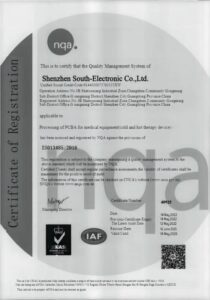
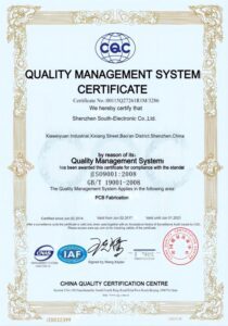
Вы получите уверенность, работая с компанией, сертифицированной по ISO9001.
Мы придерживаемся высоких стандартов и обеспечиваем прозрачное общение, гарантируя, что ваши гибкие печатные платы не только соответствуют, но и превосходят ваши ожидания по производительности, долговечности и точности. -
Комплексное обслуживание
Вы получаете полный цикл услуг – от проектирования и прототипирования до серийного производства.
Мы предлагаем единое решение, исключая сложность и дополнительные расходы, связанные с работой с несколькими поставщиками. -
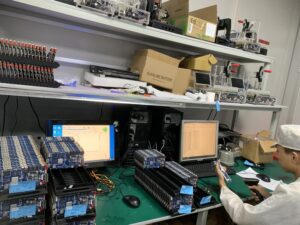
Полный спектр услуг
Вы получите полное удовлетворение благодаря нашему широкому выбору оборудования.
У нас есть все необходимые ресурсы для производства печатных плат. От разработки до доставки – мы гарантируем, что ваш заказ будет выполнен на высоком уровне. -
Быстрая доставка
Вы соблюдаете сроки благодаря нашим оперативным срокам выполнения заказов.
Оптимизированное производство гарантирует быструю обработку заказов, чтобы вы получили продукцию точно в срок, без задержек.
Реализованные нами проекты
Отзывы клиентов
Часто задаваемые вопросы
Часто задаваемые вопросы
Отправьте нам сообщение
Чем подробнее вы заполните, тем быстрее мы сможем перейти к следующему шагу.


Полное руководство по проектированию гибких печатных плат
Содержание
Глава 1
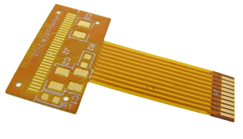
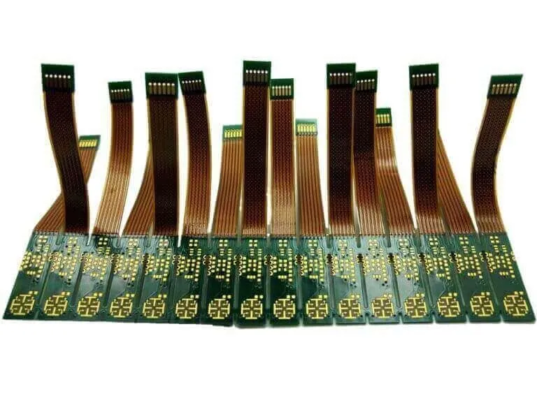
Что такое гибкие печатные платы?
Гибкие печатные платы (Flex PCBs) – это электронные схемы, изготовленные на гибких подложках, что позволяет им сгибаться, скручиваться и адаптироваться к различным формам и конфигурациям. В отличие от традиционных жестких печатных плат, которые производятся на твердых и негибких материалах, таких как стекловолокно, гибкие печатные платы изготавливаются из высокопроизводительных полимеров, таких как полиимид или полиэфирная пленка. Такая гибкость открывает множество возможностей в проектировании электроники, поскольку позволяет интегрировать схемы в устройства, где важны компактность, форма и подвижность. Они играют ключевую роль в современной электронике, обеспечивая надежные соединения в компактных и подвижных системах.
Почему стоит использовать гибкие печатные платы?
Есть множество причин. Во-первых, они позволяют создавать более компактные и легкие электронные устройства. Это означает, что можно разрабатывать более удобные и эргономичные продукты. Во-вторых, они более надежны, так как содержат меньше соединений, которые могут выйти из строя. Это критично, потому что в жестких печатных платах разрывы соединений часто происходят из-за механических нагрузок. В-третьих, они дешевле. Благодаря гибкости требуется меньше разъемов и материалов, что снижает затраты на производство и сырье.
Обзор областей применения
От бытовой электроники до аэрокосмической промышленности – гибкие печатные платы находят применение в самых разных сферах. В повседневной жизни они используются в смартфонах, передовых камерах и носимых фитнес-устройствах. В медицине они необходимы для разработки компактных и эффективных носимых медицинских устройств и имплантов. В автомобильной и аэрокосмической промышленности гибкие печатные платы помогают создавать более легкие и надежные системы. Их гибкость и малый вес способствуют повышению общей производительности и эффективности расхода топлива.
Глава 2
Материалы, используемые в гибких печатных платах
Материалы, которые можно использовать
Чтобы создавать наиболее гибкие и долговечные электронные устройства, необходимо знать, какие материалы применять. Самым распространенным материалом для гибких печатных плат является полиимид (PI). Он сохраняет гибкость при нагреве и отличается высокой прочностью. Также популярен полиэстер (PET), который дешевле и подходит для бюджетных решений, где не требуется максимальная производительность. Если вам нужна плата для работы на высоких частотах, стоит использовать жидкокристаллический полимер (LCP), так как он обладает лучшими электрическими характеристиками.
Почему важно правильно выбирать материал
Выбор материала для гибкой печатной платы – это как подбор лучших ингредиентов для кулинарного шедевра. От него зависит итоговый результат. Материал влияет на гибкость, прочность, термостойкость и электрические характеристики схемы. Например, если выбрать полиимид, печатная плата сможет выдерживать экстремальные температуры. Это делает его идеальным решением для аэрокосмической и автомобильной промышленности, где важно, чтобы устройство работало стабильно даже в сложных условиях.
Как материалы влияют на производительность
Выбранные материалы напрямую определяют, как будет работать гибкая печатная плата в реальных условиях. Например, полиимид обладает высокой термостойкостью, что критично для надежных устройств, работающих в сложных средах. В то же время полиэстер поможет снизить затраты на производство потребительской электроники, где устойчивость к высоким температурам не является приоритетом, но при этом его долговечность и термостойкость будут ниже.
Знание свойств материалов помогает проектировать гибкие печатные платы, которые точно соответствуют требованиям, обеспечивая их оптимальную производительность и надежность в любой сфере применения.
Глава 3
Принципы проектирования гибких печатных плат
Основные принципы проектирования
Проектирование гибких печатных плат похоже на работу архитектора, но вместо создания здания вы разрабатываете конструкцию, способную сгибаться и гнуться. Важно понимать свойства материалов, такие как их гибкость и прочность. Также необходимо эффективно использовать пространство, делая плату как можно меньше, но при этом не размещая компоненты слишком близко друг к другу, чтобы избежать перегрева и помех.
Ключевые факторы в проектировании гибких печатных плат
При проектировании гибкой печатной платы необходимо учитывать расположение компонентов относительно зон изгиба и обеспечивать достаточный радиус изгиба, чтобы материал не изнашивался и не ломался. Также важно поддерживать равномерную толщину в зонах гибкости, чтобы избежать слабых мест. Выбор материалов и условия эксплуатации определяют, насколько гибкой или жесткой должна быть конструкция.
Избегание распространенных ошибок в проектировании
Одна из распространенных ошибок при проектировании гибких печатных плат – это игнорирование механических нагрузок, которые испытывает плата в процессе эксплуатации. Важно разработать конструкцию таким образом, чтобы она могла многократно сгибаться без чрезмерного напряжения в одной точке. Также не следует размещать переходные отверстия (vias) или компоненты слишком близко к зонам изгиба, так как при сильном сгибании они могут повреждаться или выходить из строя.
Глава 4
Размещение цепей и компонентов
Советы по проектированию схемы
При размещении схем на гибкой печатной плате представляйте каждую дорожку и компонент как часть большой головоломки, которая должна идеально вписаться в ограниченное пространство. Используйте технологию HDI, чтобы минимизировать размер и увеличить функциональность. Тщательно планируйте пути прохождения сигналов, чтобы избежать электромагнитных помех (EMI) и обеспечить чистую и стабильную передачу данных внутри устройства.
Принципы размещения компонентов
Важно не только правильно разместить компоненты на плате, но и оптимизировать их работу и долговечность. Держите чувствительные элементы подальше от зон изгиба, чтобы избежать механических нагрузок. Используйте rigid-flex технологии, чтобы обеспечить стабильность для более тяжелых или критически важных компонентов, которым требуется дополнительная поддержка.
Оптимизация использования пространства
Чтобы максимально эффективно использовать пространство на гибкой печатной плате, думайте в трех измерениях. По возможности рассматривайте вертикальную интеграцию компонентов, что позволит рационально использовать доступную площадь. Такой подход не только уменьшает общий размер платы, но и повышает эффективность схемотехнического решения и производительность устройства.
Следуя этим рекомендациям, вы обеспечите, что ваша гибкая печатная плата будет не только компактной, но и надежной, устойчивой и полностью готовой к современным технологическим требованиям.
Глава 5

Тепловое управление в гибких печатных платах
Важность теплового управления
Эффективное управление теплом в гибких печатных платах играет ключевую роль, определяя, будет ли устройство надежным и высокопроизводительным или выйдет из строя раньше времени. Чрезмерный нагрев может привести к отказу компонентов и снижению эффективности устройства, сокращая его срок службы. Контролируя тепло, вы не только улучшаете работу продукта, но и увеличиваете его долговечность.
Решения для отвода тепла
Один из способов управления теплом – использование материалов с хорошими теплопроводными свойствами, таких как полиимид. Также можно применять тепловые переходные отверстия (виа) и тепловые подложки, чтобы отводить тепло от печатной платы. Еще один метод – обеспечение достаточного пространства вокруг нагревающихся компонентов, что способствует циркуляции воздуха и предотвращает перегрев, поддерживая безопасный температурный режим устройства.
Примеры из практики
Вот несколько примеров, демонстрирующих важность теплового управления. В носимой электронике (wearable technology) крайне важно поддерживать низкую температуру для удобства и безопасности пользователя. Практические исследования показывают, что грамотное размещение компонентов и выбор подходящих материалов помогают избежать перегрева в компактных устройствах.
Понимание и применение эффективных методов теплового управления гарантирует, что гибкие печатные платы будут работать стабильно в различных условиях, повышая их функциональность и срок службы.
Глава 6
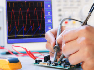
Целостность сигнала и электрические испытания
Методы поддержания целостности сигнала
Сохранение целостности сигнала в гибких печатных платах имеет решающее значение для обеспечения стабильной работы устройств. Используйте контролируемый импеданс с оптимальными параметрами ширины и расстояния между дорожками, чтобы минимизировать потери сигнала и перекрестные помехи (cross-talk). Внедряйте экранирование, особенно в схемах с высокочастотными сигналами, для защиты от электромагнитных помех (EMI).
Необходимые электрические тесты
Регулярное проведение комплексных электрических испытаний крайне важно. Они включают тестирование целостности соединений и измерение импеданса, чтобы убедиться, что схема работает корректно в различных условиях. Также применяется рефлектометрия во временной области (TDR) для выявления несоответствий импеданса и потенциальных проблем с целостностью сигнала.
Как заранее предотвратить электрические проблемы
Проектируйте схемы с учетом прогнозирования, используя инструменты моделирования, которые позволяют предсказать поведение цепей при различных электрических нагрузках. Реализация избыточности в критически важных сигнальных цепях помогает предотвратить сбои в работе. Регулярные обновления и корректировки на основе результатов тестирования обеспечат надежность конструкции и устойчивость к возможным электрическим неисправностям.
Следуя этим рекомендациям, вы не только повысите надежность ваших гибких печатных плат, но и гарантируете их долговечность и стабильность в сложных условиях эксплуатации.
Глава 7
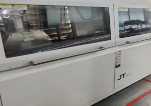
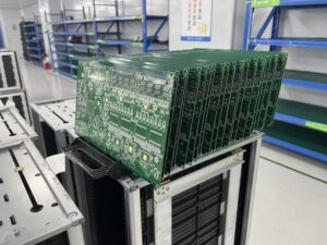
Процесс производства гибких печатных плат
Подробный процесс производства
При изготовлении гибких печатных плат сначала выбирается базовый материал – обычно это полиимид или полиэстер, обеспечивающий гибкость. Затем с помощью фотолитографических технологий высокой точности формируются схемы на поверхности материала. Для повышения долговечности наносится защитное покрытие. Далее выполняется сверление и металлизация отверстий (виа) для соединения нескольких слоев.
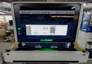
Ключевые технологии производства
Для достижения высокой точности и надежности применяются такие передовые методы, как лазерная резка и химическое травление. Также используются поверхностные покрытия, например, никель-фосфор с погружением в золото (ENIG), обеспечивающие проводимость и защиту от окисления.
Как выбрать подходящего производителя
Выбор производителя – это важный этап. Обращайте внимание на сертификацию ISO 9001, подтверждающую соответствие стандартам качества. Убедитесь, что у производителя есть опыт работы со сложными гибкими схемами и необходимые технологические возможности. Лучше выбирать компании, которые предоставляют полный цикл услуг, от проектирования до поставки, чтобы гарантировать соответствие требованиям и срокам.
Понимание процесса производства гибких печатных плат позволяет создавать качественные и надежные изделия для различных приложений. Это гарантирует стабильную работу и долговечность ваших продуктов.
Глава 8
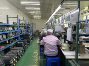
Сборка и интеграция гибких печатных плат
Технологии и стратегии сборки
При сборке гибких печатных плат важно уделять внимание точности и адаптивности. Используйте специализированное оборудование, которое учитывает особенности гибких материалов. Внедряйте технологию поверхностного монтажа (SMT) для повышения эффективности и надежности. Для компонентов, требующих дополнительной механической устойчивости, используйте защитные наполнители (underfill) для усиления соединений.
Проблемы интеграции
Интеграция гибких печатных плат в конечные устройства сопряжена с особыми трудностями из-за их чувствительности к механическим нагрузкам. Важно проектировать схему так, чтобы минимизировать напряжение в местах сгибов. На ранних этапах разработки необходимо учитывать подключение разъемов, чтобы избежать несоответствий механических и электрических интерфейсов.
Лучшие практики
По возможности применяйте модульный подход к проектированию, который упрощает тестирование и замену компонентов. Проводите тщательные испытания на гибкость и прочность в реальных условиях эксплуатации. Обеспечьте тесное взаимодействие между командами проектирования и производства, чтобы гарантировать, что печатные платы не только легко производятся, но и соответствуют всем функциональным требованиям.
Эти стратегии позволяют гибким печатным платам быть не только правильно собранными и интегрированными, но и надежными и функциональными, что значительно повышает их производительность и долговечность.

Глава 9

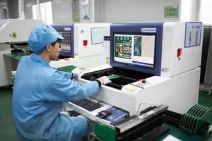
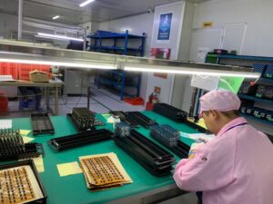
Гарантия качества и тестирование
Стандарты обеспечения качества
При разработке гибких печатных плат важно соблюдать строгие стандарты обеспечения качества. Внедряйте нормы, такие как IPC-6013, которые обеспечивают высокую надежность и производительность гибких схем. Эти стандарты регламентируют выбор материалов, проектирование, производство и тестирование, гарантируя стабильное качество продукции.
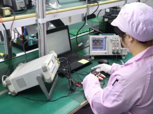
Основные методы тестирования
Используйте различные методы тестирования, чтобы проверить целостность и работоспособность гибких печатных плат. Наиболее распространенные испытания включают:
- Электрические тесты – проверка целостности цепей и изоляции.
- Механические испытания – оценка гибкости и долговечности печатной платы.
- Экологические тесты – проверка работы в условиях различных температур и влажности.
Анализ случаев
Регулярный анализ практических примеров и отзывов клиентов помогает совершенствовать процессы обеспечения качества. Исследование отказов или проблем в работающих устройствах позволяет выявлять возможности для улучшения конструкции, выбора материалов и технологий производства. Такой подход помогает заранее устранять потенциальные проблемы и повышать надежность продукции.
Интеграция эффективных стратегий тестирования и контроля качества гарантирует, что ваши гибкие печатные платы будут надежными, долговечными и соответствующими высоким требованиям в эксплуатации.
Глава 10
Будущие тенденции и инновации в технологии гибких печатных плат
Тенденции в отрасли
Индустрия гибких печатных плат стремительно развивается под влиянием спроса на более компактные и многофункциональные электронные устройства. В последние годы наблюдается значительный переход к экологически чистым материалам и технологиям. Кроме того, рост числа устройств IoT расширяет границы возможностей гибких печатных плат в плане функциональности и подключения.
Новые технологии
Появление технологий, таких как аддитивное производство, кардинально меняет процесс изготовления гибких печатных плат, позволяя создавать более сложные конструкции и минимизировать отходы. Прогресс в материаловедении, в частности в разработке проводящих чернил и инновационных подложек, повышает производительность и долговечность гибких печатных плат даже в экстремальных условиях.
Перспективные направления развития
В будущем ожидается развитие 3D-печати для производства печатных плат, что может радикально изменить производство, приблизив его к конечным пользователям и ускорив процесс кастомизации. Встраивание интеллектуальных датчиков непосредственно в гибкие печатные платы может привести к созданию более умных устройств, способных реагировать на изменения окружающей среды в режиме реального времени.
Эти будущие тенденции не только улучшат функциональные возможности гибких печатных плат, но и откроют новые перспективы для инноваций, позволяя вам расширять линейку продукции и повышать конкурентоспособность.
Связаться с Нами
Где Мы Находимся?
Промышленный Парк, № 438 Донхуан Роад, № 438, Шадзин Донхуан Роад, Район Баоань, Шэньчжэнь, Гуандун, Китай
4-й Этаж, Креативное Здание Жихуй, №2005 Сихуан Роад, Шадзин, Район Баоань, Шэньчжэнь, Китай
Комната A1-13, 3-й Этаж, Промышленный Центр Йи Лим, 2-28 Улица Kвай Лок, Квай Чунг, Гонконг
service@southelectronicpcb.com
Телефон: +86 400 878 3488
Отправьте нам сообщение
Чем подробнее вы заполните, тем быстрее мы сможем перейти к следующему шагу.

