
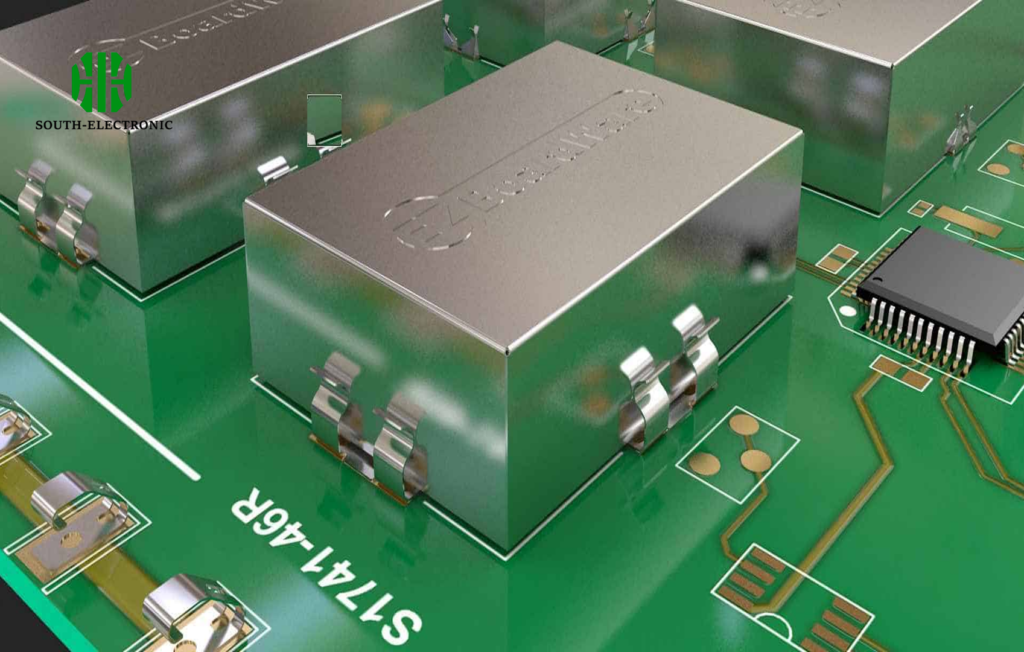
Your PCB faces two threats: electromagnetic interference that scrambles signals and environmental damage that corrodes circuits. Failing to shield correctly causes device failures and costly redesigns. Thankfully, two solutions exist—but choosing wrong risks project failure.
Shield cans suit localized EMI/RFI protection and physical impact-resistance where maintenance access is needed despite higher cost. Conformal coatings work best for thin, economical moisture/dust protection when rework is unlikely and a lightweight barrier suffices.

Both methods have nuanced tradeoffs affecting your PCB’s lifecycle. To optimize your design, we need to explore three critical implementation questions that dictate real-world performance.
Where should shield ground points go on high-speed PCBs?
Grounding mistake creates EMI antennas on your board. Signal integrity suffers and radiation escapes containment. Strategic ground point placement provides the immunity high-speed designs need.
Always place shield ground vias within 1-2mm of the shield perimeter, directly connecting to the ground plane at multiple points. This creates low-impedance paths that channel interference away from sensitive traces immediately.

Grounding Strategy Breakdown for EMI Control
Critical grounding factors include location density, plane connectivity, and loop minimization. Each impacts how effectively your shield contains interference.
| Factor | Poor Implementation | Optimal Approach | Performance Impact |
|---|---|---|---|
| Location Density | Sparse perimeter vias (>5mm apart) | Vias placed every 2-3mm along shield edge | Prevents RF leakage hotspots |
| Plane Connection | Single-layer ground connection | Multi-layer stitching to ground planes | Reduces ground impedance by 60-70% |
| Loop Area | Long return paths to components | Direct vertical links to nearest ground | Cuts induced current loops by 80% |
For GHz-range signals, ground vias must penetrate all adjacent ground layers. This avoids resonant cavities under the shield. I’ve seen 28Gbps designs fail certification due to missing backside ground stitching—forcing costly respins. Separate digital and analog ground domains under the shield boundaries when mixing signal types. Never cross split planes.
Can you bend flexible PCBs with shielding without losing performance?
Repeated flexing cracks rigid metal shields and delaminates coatings. Your bend-tolerant design becomes unreliable as shielding flakes off, exposing circuits to interference.
Yes—use either polymer-based conductive coatings under 25μm thick or patterned shield meshes. These maintain over 85% shielding effectiveness after 100+ bends by distributing stress across flex zones without rigid boundaries.

Material Performance During Dynamic Flexing
Protection degrades differently across shielding types when bending occurs. Consider these comparative metrics:
| Shielding Type | Bend Radius Limit | Cycles Before Failure | SE Loss at 1GHz |
|---|---|---|---|
| Solid Shield Can | 20mm | 40dB drop | |
| Silver Ink Coating | 5mm | 500+ cycles | <3dB drop |
| Copper Mesh | 3mm | 1,000+ cycles | <2dB drop |
In folding designs like medical wearables, avoid abrupt shield edges at bend lines—taper shielding thickness gradually over 10mm zones. I specify conductive inks for cardiac monitors subjected to daily flexing. Apply shields AFTER setting final bend points during manufacturing to prevent microcracks. Verify effectiveness using bent-state network analyzer tests.
When are EMI shielding gaskets worth the extra cost?
Gaskets seem expensive until your device fails emissions testing. Poor enclosure sealing creates radiating gaps that leak interference. The compliance risk often justifies the investment.
Gaskets pay off in high-frequency military/aerospace systems, medical devices near RF sources, and multi-chassis servers requiring 360° shielding continuity exceeding 40dB attenuation.
Cost-Benefit Decision Framework
Consider these factors when deciding between standard shields and gaskets:
| Scenario | Without Gasket | With Gasket | When to Choose |
|---|---|---|---|
| Enclosure Gap Size | 1.0mm | Choose gaskets when gaps exceed 0.5mm | |
| Frequency Range | 3GHz effectiveness | Mandatory above 2GHz | |
| Environmental Sealing | Protection absent | IP67 sealing | Critical in dusty/humid environs |
For 5G base stations, I always spec fingerstock gaskets—they solve two problems: EMI containment at mmWave frequencies and weather sealing. Calculate ROI against potential retesting fees. Metal-filled elastomers outperform traditional metal mesh gaskets by surviving 10x more compression cycles without tearing. Install them after conformal coating to avoid capillary seal-breaching.
Conclusion
Match shield cans to repairable EMI-critical areas and coatings for environmental protection. Ground shields densely in high-speed designs, flex shielding materials deliberately, and justify gaskets for RF-intensive applications requiring robust sealing.

