
Ever had an LED mysteriously quit working? That burnt smell isn’t coffee. Faulty diodes sabotage circuits daily. I’ll reveal simple testing secrets anyone can do.
To test a diode, set your multimeter to diode test mode or resistance mode. Connect red probe to anode, black to cathode: healthy diodes show 0.5-0.8V voltage drop (silicon) or low resistance. Reverse probes: good diodes display OL or high resistance.
I’ve discovered several crucial steps after frying diodes myself. Let’s explore exactly how this process works across different scenarios.
What is Diode Testing?
Seen a diode glowing suspiciously? That’s your circuit screaming for help. Diode testing spots these silent saboteurs before they kill devices.
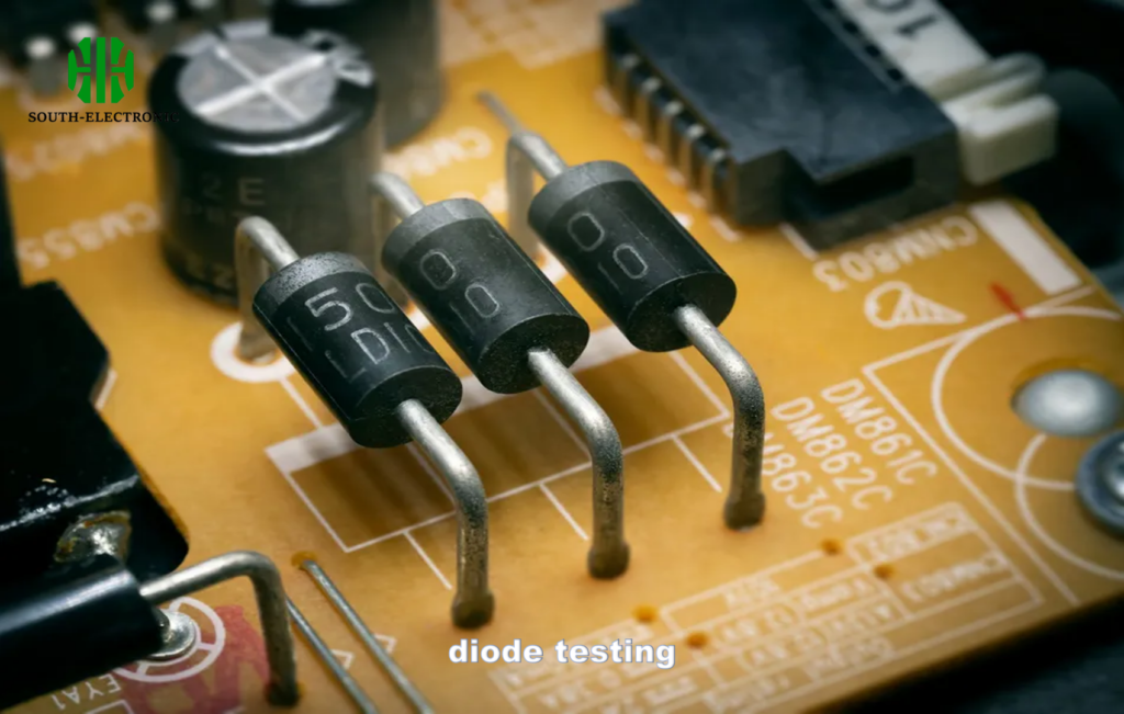
Diode testing checks if diodes block current in reverse direction and conduct in forward direction. Multimeters measure this one-way electrical behavior to confirm functionality.

Understanding Diode Functions
Diodes act as electrical one-way valves. They control current flow direction within circuits. Testing proves they work correctly.
Why Testing Matters
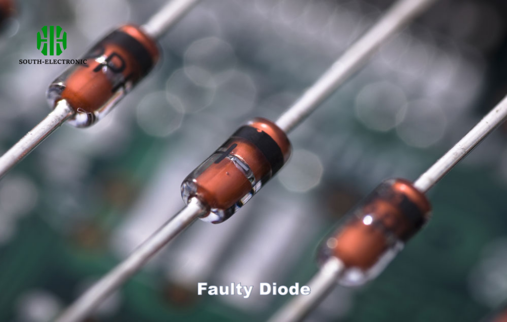
Faulty diodes cause circuit failures. Testing prevents device damage. Look for these symptoms:
| Failure Type | Forward Bias Test | Reverse Bias Test | Real-World Effect |
|---|---|---|---|
| Healthy Diode | 0.5-0.8V (silicon) | OL | Normal operation |
| Shorted | 0V | 0V | Overheating/current leaks |
| Open | OL | OL | Complete circuit failure |
| Leaky | Normal drop | Partial conduction | Erratic performance |
| Degraded | High drop (>1V) | Partial conduction | Reduced efficiency |
Catching failures early saved my amplifier project. Always test new diodes before installation. Regular maintenance checks prevent unexpected breakdowns.
How Do You Set Up Your Multimeter for Diode Testing?
Wondering why your diode test gives crazy readings? Incorrect setup causes 90% of errors. Get crystal-clear results with this sequence.
Set multimeter to diode symbol (→|) or resistance mode (Ω). Choose low resistance range if using Ω mode. Verify battery charge before starting and zero-out probes on metal surface.
Mode Selection Guide
Diode Test Mode
• Locate diode symbol (→|) on dial
• Automatic range selection
• Displays actual voltage drop
• Best method for most testing
Resistance Mode Backup
• Use if no diode mode available
• Select lowest resistance range
• Watch for automatic ranging
• Results in ohms instead of volts
Critical Precautions
Disconnect diode from circuits before testing. Power off devices completely. Ground yourself to avoid static damage. I fried three diodes before learning this.
Always test twice: flip probes between measurements. Confirm stable readings. Contaminated probes cause false readings – clean with alcohol pad.
What Are Common Diode Problems and How to Diagnose Them?
Your circuit acting possessed? Diode issues manifest as ghostly glitches. Learn to spot them like a pro without expensive tools.
Shorted diodes show 0V forward/reverse bias. Open diodes display OL both ways. Leaky diodes conduct partially when reverse-biased. Degraded diodes exhibit abnormal voltage drops during testing.
Problem Detection Process
Step-by-Step Diagnosis
First, perform diode testing with multimeter. Record forward/reverse readings. Compare against expected values. Identify mismatch patterns.
Next, examine physical condition: burnt marks, cracks, bulges. My generator diode had visible cracks that testing confirmed.
Solution Toolkit
• Shorted diodes: immediate replacement
• Open diodes: check solder connections
• Leaky diodes: urgent replacement
• Degraded: schedule soon replacement
Create test records for reference. Note voltage drops during replacements. Documenting trends helped me predict failures.
Conclusion
Testing diodes requires simple multimeter skills and pattern recognition. Check forward/reverse readings against standards. Spot problems like shorts, opens, leaks, or degradation. Keep circuits running smoothly.

