
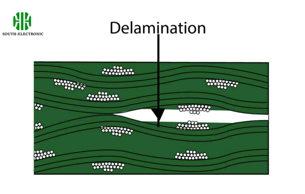
When your multilayer PCB starts delaminating after thermal cycling, you’ll wish you’d paid attention to this hidden material. PCB prepreg[^1] serves as the molecular bridge connecting circuit layers – get its properties wrong, and your entire stackup becomes unreliable.
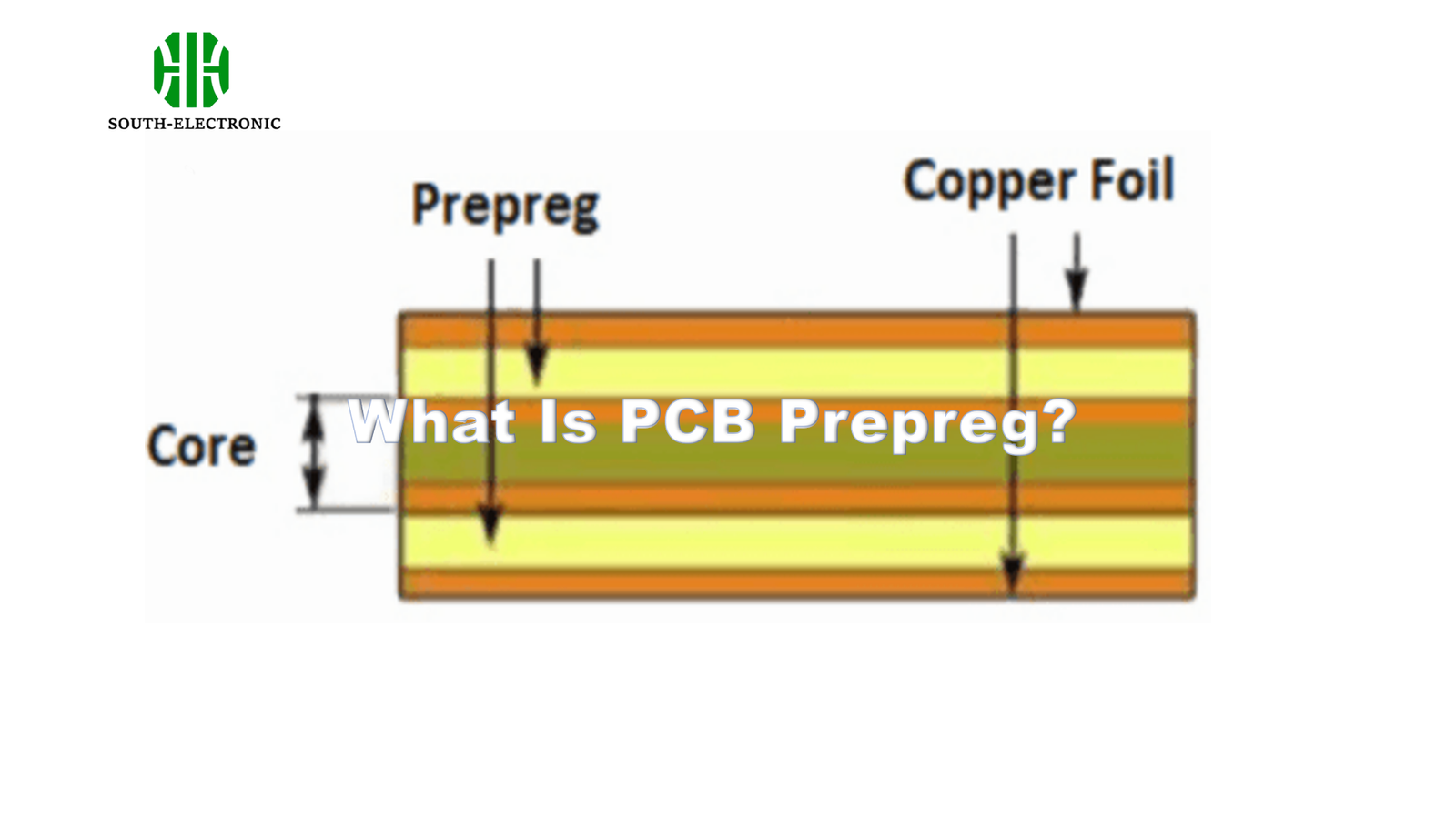
PCB prepreg is a semi-cured dielectric material that bonds conductive layers during lamination. Composed of fiberglass cloth impregnated with resin, it provides electrical insulation and structural integrity in multilayer boards. Unlike core materials, prepreg flows under heat to fill microscopic gaps.
Most engineers treat prepreg as a generic “glue,” but its technical specifications impact signal performance and manufacturing yield. Let’s dissect four critical aspects that separate successful designs from field failures.
Why Is PCB Prepreg Called the ‘Invisible Glue’ of Circuit Boards?
A military avionics PCB failed during vibration tests – all because engineers ignored the “non-critical” bonding layer. Prepreg works invisibly between etched copper layers, yet holds the entire board’s structure together after curing.
Prepreg becomes invisible post-lamination because it chemically bonds with adjacent materials, unlike physical adhesives. Its glass transition temperature (Tg)[^2] determines whether it maintains stability under thermal stress, directly affecting long-term reliability in harsh environments.
)
The Structural vs. Functional Divide
| Characteristic | Structural Role | Functional Limitations |
|---|---|---|
| Material Composition | Epoxy resin + fiberglass | No conductive particles |
| Post-Lamination State | Fully cured dielectric | Can’t conduct signals |
| Failure Modes | Delamination at 260°C+ | Doesn’t cause short circuits |
| Design Impact | Determines layer alignment precision | Affects impedance through Dk value |
The 2023 IPC-4101E standard[^3] identifies 72 prepreg classifications – using the wrong type creates Z-axis CTE mismatch. For 20-layer boards, even 2% thickness variation accumulates to 0.5mm alignment errors after lamination.
How Does Prepreg[^4] Differ from the Core[^5] in a PCB?
An automotive controller faced intermittent opens because the designer interchangeably used core and prepreg materials. The board cracked during temperature shocks due to mismatched CTE values.
Prepreg contains uncured resin for fluidity during pressing, while cores have pre-cured dielectric with copper foil. Prepreg’s lower Tg (130-180°C) allows viscoelastic flow, whereas cores maintain rigidity above 180°C to prevent distortion.
)
Material States Determine Manufacturing Outcomes
| Property | Prepreg | Core |
|---|---|---|
| Resin Curing Level | B-stage (partial cure) | C-stage (full cure) |
| Copper Bonding | Adheres during lamination | Pre-bonded foil |
| Thickness Tolerance | ±10% after flow | ±3% as supplied |
| Dk at 1GHz | 3.8-4.5 (depending on resin) | 4.0-4.7 (higher glass content) |
In high-speed designs, core-prepreg Dk mismatch[^6] causes impedance discontinuities. A 0.5 Dk difference at 56Gbps creates 12% reflection – enough to fail PCIe 6.0 compliance. Always model the actual prepreg Dk curve, not datasheet nominal values.
What Happens to Prepreg During the PCB Lamination Process?
A 5G antenna array lost 3dB efficiency due to air pockets in prepreg. The lamination profile[^7] didn’t account for the resin’s gel time, trapping voids between RF layers.
During lamination, prepreg melts at 150-200°C, flows to fill copper topography, then crosslinks into a solid. Pressure (300-500 PSI) forces resin into 3μm gaps between traces, while vacuum removes entrapped air that causes partial discharges.
)
Thermal Parameters Dictate Resin Behavior
| Stage | Temperature Range | Key Physical Change |
|---|---|---|
| Preheat | 80-120°C | Resin viscosity drops to 1000-2000 cP |
| Flow | 130-180°C | 65-85% resin flow completion |
| Cure | 190-220°C | Epoxy crosslinking achieves Tg |
| Cool Down | <50°C/hour | Prevents microcracks from CTE shock |
Autoclave lamination for aerospace PCBs uses 6-hour cycles versus 90 minutes for consumer boards. Fast-curing resins save time but increase warpage – 0.15% resin shrinkage can bow 2mm over 300mm panels.
Can Prepreg Choice Affect Signal Integrity in Your Design?
A 112G PAM4 SerDes channel showed 4dB higher loss because the designer selected FR-4 prepreg instead of ultra-low-loss Megtron 6. The 0.005 vs. 0.002 dissipation factor ruined eye diagrams.
Prepreg’s dielectric constant (Dk) and loss tangent (Df) set signal velocity and attenuation. For 10mm traces at 28GHz, 0.01 Df difference adds 1.2dB loss – pushing margins beyond IEEE 802.3ck specs for 800GbE interfaces.
)
Material Properties vs. Performance Limits
| Prepreg Type | Dk @ 10GHz | Df @ 10GHz | Max Data Rate | Humidity Absorption |
|---|---|---|---|---|
| Standard FR-4 | 4.3 | 0.020 | 6Gbps | 0.8% |
| Mid-Loss 370HR | 3.9 | 0.008 | 56Gbps | 0.4% |
| Ultralow-Loss Megtron6 | 3.5 | 0.0015 | 112Gbps | 0.2% |
Moisture absorption[^8] shifts Dk by 4% per 0.1% weight gain – for submarine cables, this requires hermetic sealing. In automotive radars, thermal Dk stability (±0.05 from -40°C to 125°C) prevents beamforming errors exceeding ±0.5°.
Conclusion
PCB prepreg selection isn’t an afterthought – its dielectric stability[^9], flow characteristics, and thermal compliance[^10] determine whether your multilayer design survives fabrication and lasts in the field. Match material specs to operational demands.
[^1]: Understanding PCB prepreg is crucial for ensuring the reliability and performance of multilayer PCBs. Explore this resource to deepen your knowledge.
[^2]: The Tg of prepreg materials is vital for thermal stability in PCBs. Learn more about its impact on reliability in this informative link.
[^3]: Familiarizing yourself with the IPC-4101E standard can help you choose the right prepreg for your designs, enhancing performance and reliability.
[^4]: Understanding Prepreg is crucial for PCB design, as it affects thermal and electrical performance. Explore this link for in-depth insights.
[^5]: Core materials are essential for PCB stability and performance. Discover more about their properties and applications in this informative resource.
[^6]: Dk mismatch can lead to significant performance issues in PCBs. Learn more about its impact and solutions in this detailed article.
[^7]: Learning about lamination profiles can enhance your understanding of the PCB manufacturing process and improve product quality.
[^8]: Understanding moisture absorption is crucial for ensuring the reliability and longevity of PCBs in various environments.
[^9]: Exploring dielectric stability can help you choose the right materials for optimal PCB performance and reliability.
[^10]: Learning about thermal compliance can guide you in selecting materials that withstand temperature variations without compromising performance.

