
Ever struggled with overheating circuits melting your projects? I watched my first LED prototype fail from heat stress. Standard PCBs couldn’t handle the thermal load, almost derailing my project timeline.
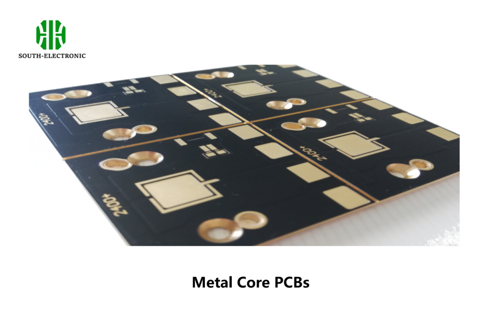
PCBs use non-conductive materials like FR4 for general circuits. Metal core PCBs[^1] (MCPCBs) use aluminum or copper bases specifically to dissipate heat in power applications like LEDs. This core difference solves thermal issues where traditional boards fail.
Choosing between these boards impacts product reliability. Let’s compare their design approaches and thermal behaviors to optimize your electronics.
How do you design an MCPCB?
Design flaws cause costly MCPCB failures. I’ve seen poorly planned layouts overheat despite metal cores. Follow these guidelines to avoid thermal traps.
Focus on heat path optimization[^2] when designing metal core PCBs. Place heat sources directly above metal cores, use minimal dielectric layers, and calculate thermal vias[^3]. Always verify copper thickness compatibility.
Critical Design Variables
MCPCB design requires balancing three elements: conductivity needs, manufacturing constraints, and cost. Below is the decision framework I use:
| Design Factor | Aluminum Core | Copper Core |
|---|---|---|
| Thermal Conductivity (W/mK) | 2-3 | 5-8 |
| Optimal Layer Count | 1-4 layers only | Up to 8 layers possible |
| Weight Comparison | Lighter | 2-3x heavier |
| Cost Relative to FR4 | 40% higher | 150% higher |
| Best For Thermals | Medium power LEDs | High-power semiconductors |
The metal core pcb manufacturing process requires specific drilling techniques. Aluminum cores need carbide bits to avoid burrs. Copper cores demand slower feed rates. Thermal conductivity drops significantly when dielectric layers exceed 0.1mm. Place heat sources away from board edges to prevent hotspots.
Why are metal core PCBs superior to standard FR-4 in thermal management?
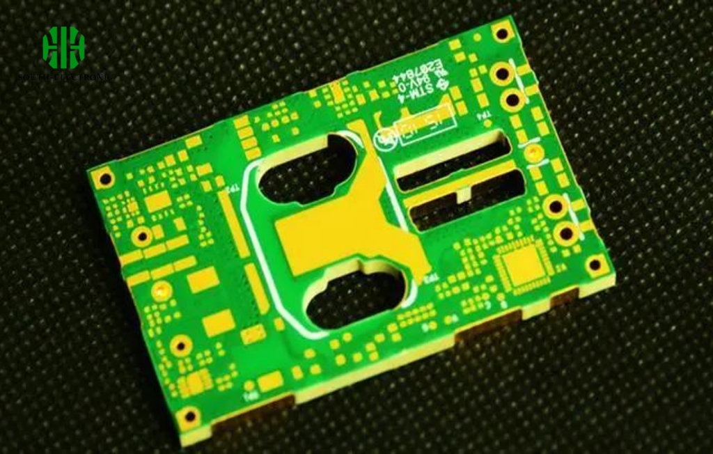
Watch FR4 boards[^4] discolor under high loads? I have. Their trapped heat damages sensitive components. Metal cores provide escape routes.
Metal core pcbs transfer heat up to 10 times faster than FR4. Their aluminum or copper bases draw heat from components directly. This prevents temperature buildup in power electronics.
Thermal Performance Breakdown
The superiority comes from three physical properties:
| Property | FR4 Board | MCPCB |
|---|---|---|
| Base Material | Glass-epoxy | Metal (Al/Cu) |
| Thermal Path | Non-linear | Direct vertical |
| Conductivity Range | 0.2-0.3 W/mK | 1-400 W/mK |
| Failure Threshold | 130°C | 140-300°C |
| Component Lifespan | Shortens by 50% over 85°C | Maintained at 100°C |
FR4 traps heat between non-conductive layers. Metal core pcb thermal conductivity[^5] creates direct paths from components to heatsinks. I use aluminum cores for automotive controllers surviving 120°C environments. Copper cores handle extreme loads like server power supplies. Thermal vias must connect directly to the metal base to work properly.
When should you choose aluminum core PCB over copper, or vice versa?
Picking the wrong core type wastes budget. I recall a client overspending on copper when aluminum sufficed. Learn when each metal works best.
Pick aluminum for cost-sensitive light products. Choose copper for extreme thermal demands when budget permits. Aluminum cores serve most lighting apps well. Copper suits military-grade thermal requirements.

Material Selection Matrix
Trade-offs determine metal choice:
| Requirement | Aluminum Core Solution | Copper Core Solution |
|---|---|---|
| Budget Limitation | Yes, cheaper | No, premium |
| Ultra-Thin Designs | Difficult | Better flexibility |
| Power Density | Below 8W/cm² | Above 10W/cm² |
| RF Applications | Poor performance | Excellent due to conductivity |
| Weight Concerns | Lighter | Substantially heavier |
| Thermal Spikes | Good for moderate ✅ | Required for extreme ✅ |
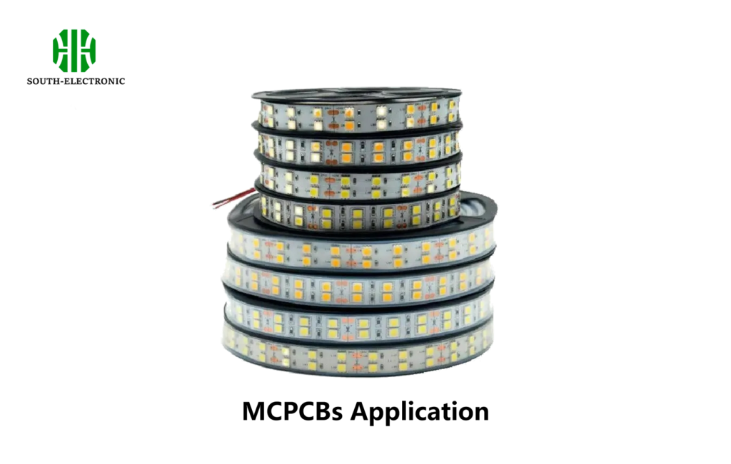
Aluminum cores dominate LED applications – 70% of my lighting projects use aluminum clad boards. Copper becomes necessary when dealing with power semiconductors exceeding 150W. Copper MCPCB stackups support more layers but increase fabrication complexity. Always prototype both when unsure.
Conclusion
PCB versus MCPCB boils down to thermal needs. Metal cores manage heat for high-power electronics using optimized stacks. Choose bases wisely based on cost and conductivity requirements.
[^1]: Explore the benefits of Metal core PCBs for efficient thermal management in electronics.
[^2]: Learn about heat path optimization techniques to enhance the performance of your PCBs.
[^3]: Gain insights into thermal vias and their role in effective heat dissipation in PCBs.
[^4]: Explore the drawbacks of FR4 boards and why alternatives like MCPCBs are preferred.
[^5]: Understanding thermal conductivity is crucial for optimizing PCB designs and ensuring reliability.

