
Ever tried cramming bulky wires into a smartphone? Space vanishes instantly. That panic drives us toward smarter solutions like FPC connectors—tiny heroes saving our shrinking gadgets.
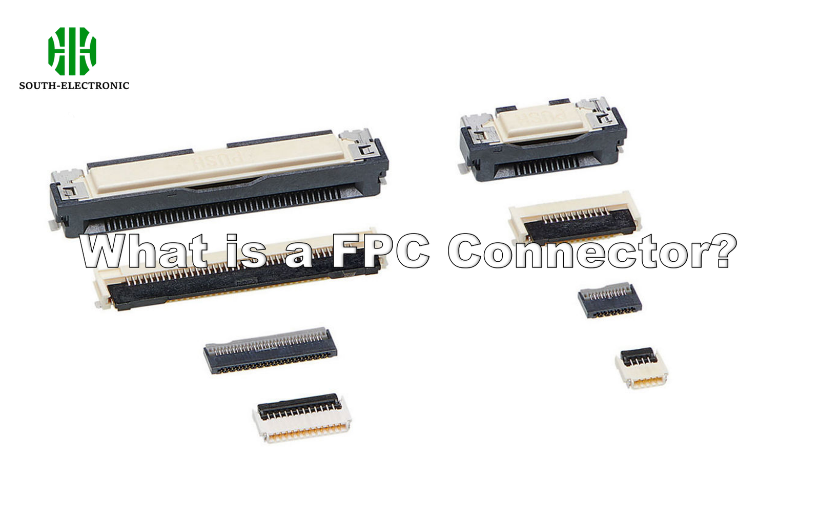
An FPC connector electrically links flexible printed circuits[^1] (FPCs) or flat cables to rigid PCBs. Its ultra-thin, bendable design solves space constraints in compact electronics like phones and laptops while maintaining reliable signal transmission[^2] for dynamic applications.
Understanding what a flex connector pcb does is step one. Now, let’s explore how to wield these compact marvels effectively—and avoid costly mistakes when integrating them.
How to design with FPC connectors successfully?
Frustrated by sudden disconnections mid-assembly? Flaws in FPC connector integration can kill functionality instantly. My strategy prevents these nightmares before they start.
Ensure perfect alignment between connector pins and cable contacts while adding strain relief anchors. Double-check insertion depth specifications and bake polarization features into your design so cables mate correctly on the first try, every time.

Critical Design Factors for Reliable FPC Integration
Success demands balancing mechanical stability with electrical performance. Follow these core principles:
Bend Radius Management[^3]
| Bend Type | Max Radius | Failure Risk |
|---|---|---|
| Static installation | 3x cable thickness | Low |
| Dynamic flexing | 10x cable thickness | High |
Never exceed manufacturer-recommended angles. Install adhesive-backed stiffeners near flex connector pcb joints to distribute stress. I once saw an overbent ffc vs fpc cable crack in a drone gimbal, paralyzing the camera.
Contact Pressure Optimization[^4]
Too little pressure = intermittent signals. Too much = crushed contacts. I use gold-plated sockets for low-resistance mating and specify 0.2N~0.5N per-contact force through connector specs. Test mating cycles early with prototype cables.
Environmental Hardening[^5]
Sealing isn’t optional for automotive uses. Apply urethane conformal coating when moisture threatens connectivity. In dusty factories, I use IP-rated connectors with wipe-clean seals – a basic flat flex connector upgrade preventing 80% of particle-related jams based on client feedback.
What are common FPC connector failures?
A flickering smartwatch display often screams connector failure. I’ve teardowned hundreds of devices to uncover recurring nightmares beneath sleek casings. Knowledge cuts repair costs by 60%.
Top failures include cracked solder joints from mechanical stress, contact oxidation causing voltage drops, and cable tears from sharp bends. Humidity-induced corrosion plagues exposed connecteur fpc units while misalignment shreds contacts during mating.
Decoding Failure Modes and Correction Tactics
Breakdowns follow predictable patterns. Combat them systematically:
Mechanical Stress Failures
| Symptom | Root Cause | Fix |
|---|---|---|
| Intermittent disconnects | Vibration loosening | Add latch locks |
| Cable tears | Overflexing near connector | Install strain relief loops |
| Broken solder joints | Thermal cycling stress | Use flexible epoxy underfill |
Anchor all fpc connectors via SMT pads plus through-hole pegs. I once fixed gaming controller disconnects by adding 1mm foam under connectors to absorb impact shocks.
Contamination & Wear
Environmental grime accelerates decay. Gold plating wears thin after 5,000+ cycles in industrial controls. For chemical plants, I swap standard flat flex connector models for nickel-plated versions with silicone seals. Clean contact surfaces quarterly using non-residue solvents.
Electrical Degradation
Signal loss spikes when tin contacts oxidize. Test contact resistance monthly in humid climates. Migrate to redundant dual-contact modules for mission-critical medical devices. Temperature monitoring helps predict ffc vs fpc cable breakdowns – resistance jumps 15% before total failure.
How do you choose the right FPC connector?
Facing shelves overflowing with connecteur fpc options? Random picks guarantee production delays. My four-step system eliminates guesswork while meeting project budgets.
Prioritize pitch alignment (0.3mm/0.5mm/1.0mm), confirm current/pin capabilities (0.5A~3A), then validate mechanical specs like mating cycles (500 vs 10,000+). Lastly, match environmental ratings to deployment conditions.
Selection Framework Through Critical Filters
Simplify complex choices with this structured approach:
Pitch & Density Analysis
| Contacts | Pitch Options | Use Case |
|---|---|---|
| 10-20 pin | 1.0mm | Basic button controls |
| 20-50 pin | 0.5mm | Camera modules |
| 50-100+ pin | 0.3mm | High-res displays |
Measure existing flex cables first—mismatched pitch causes irreparable insertion damage. For drone motor controllers, I combine high-density fpc connectors with thinner 0.2mm polyimide films.
Electrical & Signal Requirements
Confirm voltage/current demands before current-carrying capacity. High-speed data? Impedance-controlled options maintain signal integrity above 5Gbps. Never pair power-hungry motors with low-amperage flex connector pcb units. I simulate loads using manufacturer SPICE models pre-purchase.
Environmental Survivability
| Environment | Connector Feature | Durability Boost |
|---|---|---|
| High humidity | Gold plating & seals | Prevents corrosion |
| Vibration zones | Metal latch locks | Stops disconnects |
| Temperature swings | Liquid crystal polymer housing | Resists warping |
Automotive projects demand -40°C to 125°C ranges. Consumer goods thrive with cheaper -25°C to 85°C materials. Verify certifications like IP67 when liquids threaten flat flex connector reliability.
Conclusion
FPC connectors bridge rigid PCBs to flexible circuits in slim devices. Mastering their design, failure patterns, and selection ensures robust, lasting electronics – ready for tomorrow’s miniaturization challenges.
[^1]: Learn about the advantages of flexible printed circuits in compact device design.
[^2]: Understand the importance of reliable signal transmission in electronic devices.
[^3]: Find out how managing bend radius can prevent failures in flexible circuits.
[^4]: Learn how optimizing contact pressure can enhance connector performance.
[^5]: Explore methods to protect connectors from environmental factors.

