
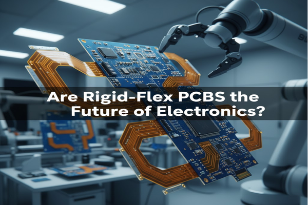
Are you tired of bulky, unreliable electronic devices? Rigid-flex PCBs offer a solution, combining the best of rigid and flexible circuit boards.
Rigid-flex PCBs integrate rigid and flexible circuits, giving you space savings[^1], higher reliability[^2], and better performance[^3] in compact designs. They reduce assembly complexity and boost signal integrity.
I remember when I first saw a rigid-flex design. It changed how I thought about electronics. Let's explore why these boards are so important.
How is a Rigid-Flex PCB Made?
Ever wonder how tiny, complex electronics fit together? Rigid-flex PCBs are a marvel of engineering, merging different materials into one seamless unit.
Rigid-flex PCBs are made by laminating flexible circuit layers with rigid ones, using adhesives and heat. This creates a single, durable board with both fixed and bendable sections.

Making a rigid-flex PCB involves several precise steps. First, engineers design the layout. This includes both the rigid and flexible parts. The flexible layers use materials like polyimide. Rigid layers use FR-4[^4], a common PCB material. These layers are prepared separately. Then, they are stacked. Adhesives bond them together under heat and pressure. This creates a strong, unified structure. Holes are drilled through the entire assembly. This connects different layers electrically. Copper traces are then etched onto the layers. A protective solder mask covers the traces. Finally, surface finishes are applied. These steps ensure a robust, functional board. My early projects often suffered from bulky wiring. Rigid-flex changed that completely for me.
| Step | Description | Key Material |
|---|---|---|
| Design | Layout planning for rigid and flexible sections | CAD software |
| Material Prep | Cutting and cleaning of polyimide[^5] and FR-4 | Polyimide |
| Lamination | Bonding layers with adhesives under heat | Adhesives |
| Drilling | Creating holes for interconnections | Drills |
| Etching | Forming copper traces | Copper |
| Solder Mask | Applying protective layer | Solder mask |
| Surface Finish | Enhancing solderability and protection | ENIG, HASL |
How Do Rigid-Flex PCBs Differ From Traditional Rigid PCBs?
Do you struggle with fitting complex electronics into small spaces? Traditional rigid PCBs have limitations that rigid-flex boards overcome.
Rigid-flex PCBs combine the multi-layer capability of rigid boards with the flexibility of flex circuits. This allows for dynamic bending and compact 3D packaging[^6], unlike static rigid boards.

Traditional rigid PCBs are excellent for stable, flat applications. They use FR-4 material, offering good electrical and mechanical properties. However, their fixed shape limits design freedom. Rigid-flex PCBs offer a different path. They allow parts of the board to bend and move. This is key for small, portable devices. I once worked on a wearable device. A rigid PCB would have made it uncomfortable. Rigid-flex allowed it to conform to the body. This flexibility means better space utilization. It also reduces the need for connectors and cables. Fewer connectors mean higher reliability. It also means lower assembly costs. Rigid-flex boards handle high-speed signals well. Their controlled impedance helps maintain signal integrity.
| Feature | Rigid PCB | Rigid-Flex PCB |
|---|---|---|
| Flexibility | None | Yes, in designated flexible areas |
| Space Utilization | Limited by 2D plane | Excellent, 3D packaging possible |
| Interconnections | Requires cables and connectors | Integrated, fewer external connections |
| Reliability | Good | Higher due to fewer connections |
| Assembly Complexity | Moderate | Lower, fewer manual connections |
| Cost | Generally lower | Generally higher due to complex manufacturing |
| Applications | Computers, consumer electronics | Medical implants, aerospace, wearables |
What Are the Challenges in Designing Rigid-Flex?
Thinking about using rigid-flex PCBs but worried about the hurdles? Designing these advanced boards comes with unique difficulties you should know.
Designing rigid-flex PCBs involves complex considerations like bending radius, material choices, and routing constraints. Engineers must manage signal integrity and manufacturing challenges carefully.

Designing rigid-flex PCBs presents several key challenges. One major factor is the bending radius[^7]. The flexible parts have limits on how sharply they can bend. Exceeding this can damage the circuit. Bending fatigue is another concern. Repeated bending can cause cracks in the copper traces. Careful material selection is vital. Different polyimide types have different flexural endurance. I learned this the hard way on a project where we chose the wrong material. Layout constraints are also tight. Placing components on the flexible parts is tricky. Routing traces across the rigid-flex interface needs precision. Signal integrity is critical. Bends and material changes can affect signal speed and quality. Electromagnetic interference (EMI) can also be an issue. Manufacturing these boards is more complex. Special tools and processes are needed. This drives up cost. Yield can be lower than with rigid boards. All these points require careful planning and expertise.
| Challenge | Description | Mitigation Strategy |
|---|---|---|
| Bending Radius & Fatigue | Limits on how sharp bends can be; repeated stress | Follow manufacturer guidelines; use appropriate materials |
| Material Selection | Choosing correct polyimide, adhesives, rigid sections | Consult material datasheets; consider application needs |
| Layout Constraints | Component placement and trace routing challenges | Use specialized CAD tools; plan for 3D form factor |
| Signal Integrity | Maintaining signal quality through bends | Impedance control; differential pair routing; simulation |
| EMI (Electromagnetic Interference) | Noise generation or susceptibility | Shielding layers; proper grounding; component placement |
| Manufacturing Complexity | Specialized processes and tools needed | Work with experienced fabricators; DFM analysis |
| Cost & Yield | Higher manufacturing cost; potential for lower yield | Optimize design for manufacturability; volume production |
Conclusion
Rigid-flex PCBs offer significant advantages in modern electronics but demand careful consideration of their unique design and manufacturing challenges.
[^1]: Learn how Rigid-Flex PCBs optimize space in electronic devices, enhancing design efficiency. [^2]: Discover the reliability benefits of Rigid-Flex PCBs in reducing connection failures. [^3]: Find out how Rigid-Flex PCBs enhance performance in compact electronic applications. [^4]: Understand the significance of FR-4 material in traditional and Rigid-Flex PCBs. [^5]: Discover the role of polyimide in enhancing the flexibility and durability of Rigid-Flex PCBs. [^6]: Understand the concept of 3D packaging and how Rigid-Flex PCBs enable it. [^7]: Learn how bending radius affects the design and functionality of Rigid-Flex PCBs.

