
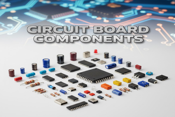
Ever wondered what makes electronics tick? Those green boards packed with tiny parts are circuit boards. Without their components, they're just pretty pieces of fiberglass.
Circuit board components are the essential building blocks that enable electronic devices to function, ranging from simple resistors to complex integrated circuits, all working together to process signals and power devices.
When I first started tinkering with electronics, the sheer number of different components on a circuit board seemed overwhelming. But understanding what each part does is key to unlocking the magic of modern technology. Let's dive deeper into these miniature marvels.
What are the common electronic components on PCB?
Feeling lost in a sea of tiny parts on your circuit board? You're not alone. Identifying these common components is the first step to understanding how your gadgets work.
Common electronic components on PCBs include passive types like resistors, capacitors, and inductors, and active components[^1] such as transistors and integrated circuits, each performing specific roles in the circuit's operation.
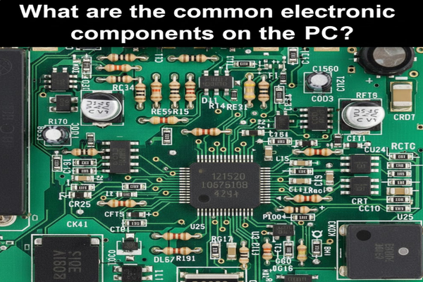
Understanding the common electronic components on a Printed Circuit Board (PCB) is fundamental. I categorize them into passive, active, and electromechanical.
Passive Components
Passive components do not generate power but store or dissipate energy.
| Component | Function | Symbol |
|---|---|---|
| Resistor | Limits current flow | R |
| Capacitor | Stores electrical energy | C |
| Inductor | Stores energy in magnetic field | L |
Active Components
Active components can control current or amplify signals, often requiring an external power source.
| Component | Function | Symbol |
|---|---|---|
| Transistor | Amplifies or switches electronic signals | Q or T |
| Diode | Allows current in one direction | D |
| Integrated Circuit | Multiple components on a chip | IC |
Electromechanical Components
These components provide physical interfaces or control.
| Component | Function | Symbol |
|---|---|---|
| Connector | Joins electrical circuits | J or CN |
| Switch | Opens or closes a circuit | SW |
| Relay | Electrically operated switch | K or RY |
These basic distinctions helped me immensely when I began designing my first custom PCBs. Knowing the role of each component is like knowing the alphabet before writing a book.
How to place PCB components?
Struggling with where to put all those tiny parts on your PCB? Proper component placement is more than just fitting everything; it's critical for performance.
Effective PCB component placement involves considering signal integrity[^2], thermal management[^3], manufacturability[^4], and electromagnetic compatibility[^5] to ensure optimal circuit performance and reliability.
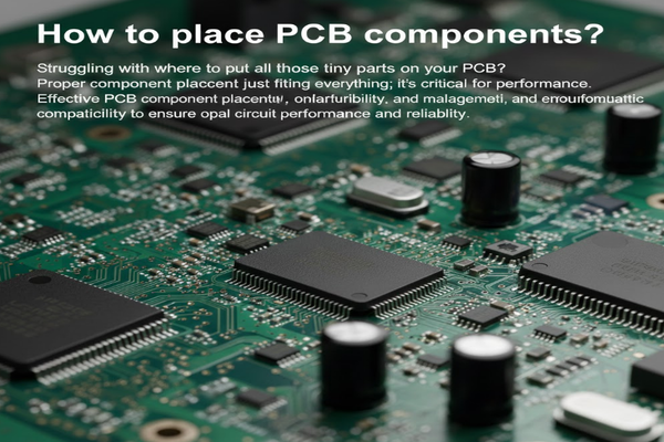
Component placement on a PCB is an art and a science. When I was learning, I realized it impacts everything from signal quality to heat dissipation.
Key Considerations for Placement
- Signal Integrity: Keep high-speed signals short and away from noise-sensitive traces. Avoid sharp bends.
- Thermal Management: Place heat-generating components (like power regulators) where they can dissipate heat efficiently, often near the board edge or with sufficient spacing.
- Manufacturability: Ensure enough space between components for automated assembly and soldering. Consider component orientation for reflow soldering.
- Electromagnetic Compatibility (EMC): Group components with similar functions. Isolate noisy digital circuits from sensitive analog circuits to prevent interference.
- Power Distribution: Place decoupling capacitors close to the power pins of ICs to reduce noise.
- Mechanical Constraints: Account for connectors, mounting holes, and enclosure clearances.
Placement Workflow
- Define board outline and mounting holes.
- Place connectors at the board's edge.
- Position critical components (e.g., microcontrollers, high-speed interfaces).
- Place power supply components near their respective circuits.
- Distribute passive components (resistors, capacitors) close to the ICs they support.
- Optimize for routing: Leave space for traces and vias.
I learned that a well-planned layout saves countless hours in debugging and ensures the final product functions as intended.
How to find shorted components on PCB?
A sudden failure, smoke, or simply a non-functional device often points to one culprit: a short. Finding a shorted component on a PCB can be a real headache.
To find shorted components on a PCB, use a multimeter[^6] to check for continuity between suspected points, visually inspect for damage, and employ thermal camera[^7]s or freeze spray[^8] to identify overheating components.
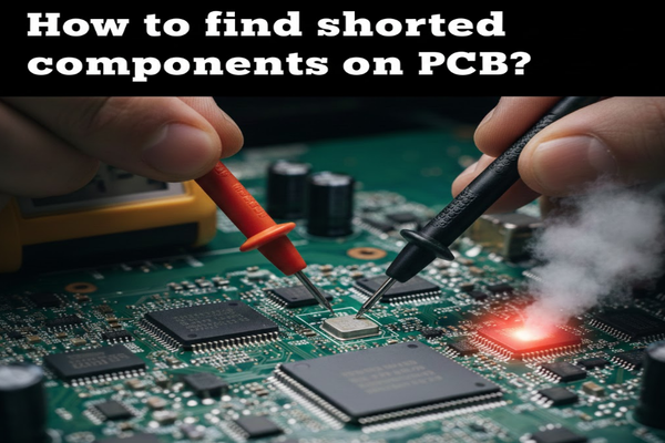
Discovering a shorted component on a PCB can be frustrating, but I've developed a systematic approach that makes the process much more manageable.
Tools and Techniques
- Multimeter:
- Continuity Check: Set to continuity mode. Touch probes to ground and suspected shorted lines. A beep indicates a short to ground.
- Resistance Measurement: Measure resistance between power and ground rails. A very low resistance (near 0 ohms) suggests a short.
- Visual Inspection:
- Look for burnt spots, discolored components, or solder bridges. These are often obvious signs of a short.
- Inspect for any bent pins or foreign objects bridging connections.
- Thermal Camera or Finger Test:
- Apply a low voltage (current-limited) to the suspected shorted line. The shorted component will heat up rapidly.
- Caution: Use low voltage and current to avoid further damage or injury.
- Freeze Spray (or Isopropyl Alcohol):
- Spray a thin layer over the PCB. When power is applied (briefly and current-limited), the shorted component will heat up and evaporate the spray first.
- Current Injection:
- Inject a small, controlled current into the shorted rail. Use a multimeter to measure voltage drop across traces to pinpoint the exact location of the short. The voltage drop will be lowest closest to the short.
My Personal Experience
I once spent hours trying to find a short on a custom power supply board. After visual inspection and continuity checks failed, I used a thermal camera. To my surprise, a tiny ceramic capacitor, which looked perfectly fine, was getting incredibly hot. Replacing it fixed the entire board. This taught me that sometimes, the fault isn't visible to the naked eye. Patience and a systematic approach are key.
3 Conclusion
Understanding PCB components, their placement, and how to troubleshoot them is crucial for anyone engaging with electronics.
[^1]: Discover the role of active components such as transistors and integrated circuits in controlling and amplifying signals. [^2]: Explore the importance of signal integrity in ensuring high-performance electronic circuits. [^3]: Learn about thermal management techniques to prevent overheating and ensure circuit reliability. [^4]: Discover how manufacturability affects the production process and quality of PCBs. [^5]: Explore EMC principles to minimize interference in electronic devices and improve performance. [^6]: Understand how to effectively use a multimeter for diagnosing issues in electronic circuits. [^7]: Learn how thermal cameras can help detect overheating components and diagnose circuit issues. [^8]: Explore how freeze spray can assist in identifying shorted components during troubleshooting.

