
What is PCB Milling, and Why Should You Care?
Suffering from slow prototype cycles? Tired of messy chemical etching for your circuit boards? There's a better way.
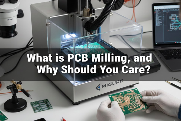
PCB milling[^1] is a subtractive manufacturing process[^2]. It uses a CNC machine[^3] to remove copper layers from a PCB's surface, creating circuit patterns. This mechanical method is ideal for quick, precise prototyping and small-batch production.

I remember when I first discovered PCB milling. It felt like a game-changer, speeding up my projects dramatically. If you're ready to ditch the chemicals and embrace precision, keep reading. We'll explore how this technology can transform your electronics work.
What is CNC mainly used for in PCB production?
Struggling with inconsistent drill holes or poorly cut boards? CNC technology offers precision you can't get by hand.
In PCB production, CNC machines are primarily used for drilling, routing, contouring, and directly milling circuit patterns. This automation ensures high accuracy and repeatability for crucial board features.

I’ve personally seen how CNC automation transforms PCB manufacturing, especially for prototyping. It takes away the guesswork and delivers consistent results every time. Let's delve into its specific applications and benefits.
Drilling: Precision Holes for Components
CNC drilling is fundamental for PCBs. It ensures accurate placement and size of holes for through-hole components and vias.
| Hole Type | Purpose | CNC Benefit |
|---|---|---|
| Via Holes | Electrical connection between layers | High precision for reliable circuits |
| Component Holes | Mounting through-hole components | Exact fit, easy assembly |
| Mounting Holes | Board attachment | Consistent sizing and placement |
Rotation and Contouring: Shaping the Board
After the circuitry is made, CNC machines cut individual boards from larger panels. This process is called routing or contouring.
PCB Pattern Milling: Direct Circuit Creation
CNC milling can directly create circuit patterns. It removes copper from selected areas, a method often called isolation milling. This method is particularly efficient for rapid prototyping.
How to fix a PCB fault quickly and efficiently?
Ever had a PCB project fail due to a simple error? Troubleshooting can be a nightmare without the right approach.
Fixing a PCB fault[^4] involves systematic steps: visual inspection[^5], testing components, checking continuity, and repairing connections. A methodical approach saves time and prevents further damage.

I’ve spent countless hours debugging PCBs, and I've learned that a structured approach is key. Don't just randomly poke around with a multimeter. Let's look at the best practices for diagnosing and repairing common PCB issues.
Initial Inspection: The First Line of Defense
Always start with a thorough visual check. Look for obvious signs of damage.
- Burn Marks: Indicates overheating or short circuits.
- Cracked Traces: Can break electrical connections.
- Cold Solder Joints: Appear dull or lumpy, leading to intermittent contact.
- Component Damage: Bulging capacitors or discolored resistors.
Testing Components: Isolate the Problem
Use a multimeter to test individual components.
| Component | Test Method | Expected Result |
|---|---|---|
| Resistors | Measure resistance | Matches marked value |
| Capacitors | Measure capacitance/Continuity | Charges/No continuity (unless shorted) |
| Diodes | Diode test mode | Conducts in one direction |
| Transistors | Diode test mode | Specific readings for junctions |
Continuity Checks: Tracing the Path
Use the continuity mode on your multimeter to ensure traces are intact and connections are solid. Look for unintended shorts between traces.
Repair Techniques: Bringing it Back to Life
Once you've identified the fault, careful repair is essential.
- Resoldering: For cold joints or loose components.
- Trace Repair: Use jumper wires or conductive ink for broken traces.
- Component Replacement: Desolder faulty parts and install new ones.
Which is better: CNC or PLC for industrial automation?
Confused about whether to use CNC or PLC for your next automation project? Choosing the wrong one can cost time and money.
CNC (Computer Numerical Control) is ideal for complex, multi-axis machining tasks requiring high precision. PLC (Programmable Logic Controller) excels at sequential control, logic operations, and discrete event management in industrial processes.

When I'm designing an automated system, the choice between CNC and PLC is critical. They serve different, though sometimes overlapping, purposes. Understanding their strengths helps you pick the right tool for the job. Let’s break down when to use which.
CNC: Precision Motion Control
CNC systems are specialized for controlling machine tools.
- G-code and M-code: These are the languages CNC machines understand, defining precise movements and actions.
- Interpolation: CNC can move multiple axes simultaneously in coordinated paths (linear, circular).
- Applications: Milling machines, lathes, laser cutters, 3D printers, all benefit from CNC's exact motion control.
| Feature | CNC |
|---|---|
| Primary Use | Complex motion control |
| Precision | Very high |
| Tasks | Cutting, shaping, machining |
| Programming | G-code, M-code |
| Data Flow | Continuous, interpolated |
PLC: Logic and Sequential Control
PLCs are robust industrial computers designed for automation of electromechanical processes.
- Ladder Logic: This is a common programming language for PLCs, mimicking relay logic circuits.
- Discrete I/O: PLCs manage on/off signals from sensors and actuators.
- Applications: Assembly lines, robotic control, process automation (e.g., controlling pumps, valves).
| Feature | PLC |
|---|---|
| Primary Use | Logic, sequencing, discrete control |
| Precision | Timing, state management |
| Tasks | On/off control, safety interlocks |
| Programming | Ladder Logic, Function Block |
| Data Flow | Discrete, event-driven |
Conclusion
PCB milling offers a precise, chemical-free way to prototype and produce circuit boards. Understanding CNC applications, fault finding, and the CNC vs. PLC[^6] debate enhances your approach to electronics.
[^1]: Explore how PCB milling can streamline your prototyping process and enhance precision. [^2]: Discover the principles of subtractive manufacturing and its role in creating PCBs. [^3]: Learn about the advantages of using CNC machines for accurate and efficient PCB manufacturing. [^4]: Get insights into troubleshooting PCB faults effectively and efficiently. [^5]: Discover how visual inspection can help identify issues before they escalate. [^6]: Understand the key differences to choose the right technology for your automation needs.

