
Tiny gaps plague PCB designers when connecting modules. Solder bridges fail, repairs frustrate, and bulky connectors waste space. Castellated holes solve these problems by creating built-in mounting points for secure, low-profile interconnections.
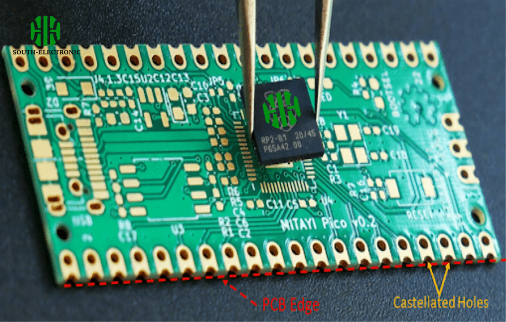
Castellated holes are semi-plated notches along PCB edges that enable direct board-to-board soldering. They eliminate dangling wires and oversized connectors, forming stable electrical connections while saving space in modular designs.
These unique features make castellated holes essential for modern electronics. But how exactly do they improve designs? Let’s explore their applications, standards, and strategic advantages.
How Do Castellated Holes Improve PCB Modular Design?
Ever struggled to connect sensor modules without messy wiring? Castellated holes act as built-in solder points, letting you stack PCBs like LEGO bricks.
Castellations allow direct soldering of daughterboards to motherboards, creating compact modular systems. They improve signal integrity by shortening connection paths and reduce failure points compared to ribbon cables or headers.
Key Benefits of Castellated Modular Design
| Aspect | Traditional Method | Castellated Solution |
|---|---|---|
| Space Use | Bulky connectors add height | Flat stacking saves 3D space |
| Reliability | Wires fatigue over time | Direct soldering resists vibration |
| Cost | Extra connectors needed | Fewer components required |
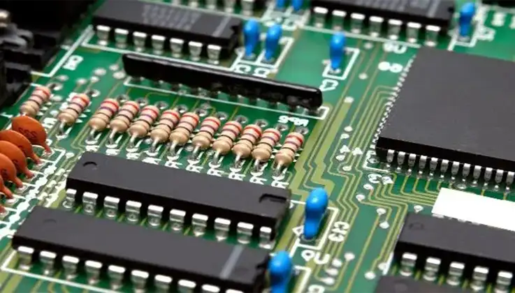
For example, IoT devices often use castellated Wi-Fi modules. Manufacturers solder them directly to mainboards, avoiding fragile connectors. The castellations’ plated edges ensure proper solder flow, while their spacing prevents short circuits. This approach works best for small-to-medium boards, as large PCBs may warp during soldering.
What Standards Govern Castellated Hole Manufacturing?
Mishapen holes ruin entire batches. Without clear specs, castellations crack or fail conductivity tests.
IPC-7351 and IPC-A-600 define castellated hole requirements. They specify plating thickness, annular ring width, and notch geometry to ensure mechanical strength and electrical continuity.
Critical Castellation Standards
| Standard | Focus Area | Requirement |
|---|---|---|
| IPC-7351 | Land pattern design | 0.2mm minimum copper wrap |
| IPC-A-600 | Plating quality | 25μm minimum hole plating |
| IPC-6012 | Final product acceptance | No cracks in solder joints |
Vendors often add 0.5mm pads beyond hole edges to compensate for drilling tolerances. I once saw a prototype fail because the fabricator used standard via specs – the thin plating cracked during soldering. Always specify “castellated holes” in your manufacturing notes to trigger special processing.
When Should You Choose Castellations Over Edge Connectors?
Edge connectors wobble. Dust settles in their slots. Yet swapping to castellations isn’t always better – context matters.
Use castellations for permanent, space-constrained assemblies. Choose edge connectors for frequently disconnected modules or high-pin-count interfaces.

Decision Guide: Castellations vs Connectors
| Factor | Castellations | Edge Connectors |
|---|---|---|
| Repairability | Hard to desolder | Easy unplugging |
| Durability | Excellent for static use | Better for frequent mating |
| Pin Density | Limited by board edge | Supports 100+ pins |
In a drone controller project, we used castellations for the GPS module (permanent) but kept USB ports as edge connectors. The hybrid approach balanced reliability with serviceability.
Conclusion
Castellated holes enable compact, reliable board stacking in modern electronics. They shine in space-sensitive designs but require adherence to IPC standards and careful use-case evaluation against traditional connectors.


