
Struggling with weak wireless signals on your PCB? Dead zones ruin user experience. Let’s fix your antenna selection fast.
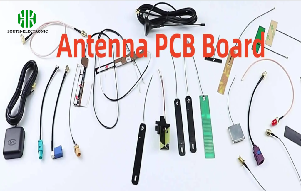
Key antenna types include monopole for simplicity, specialized shapes like shark fin for space-constrained designs, and other variants balancing cost vs performance in IoT/WiFi devices.
Choosing the right antenna is just step one. Now, uncover how to optimize its design for real-world use.
How to Calculate PCB Antenna Dimensions for Optimal Frequency?
Ever get poor signal due to wrong antenna length? Wasted space hurts reliability. Calculate dimensions right now.
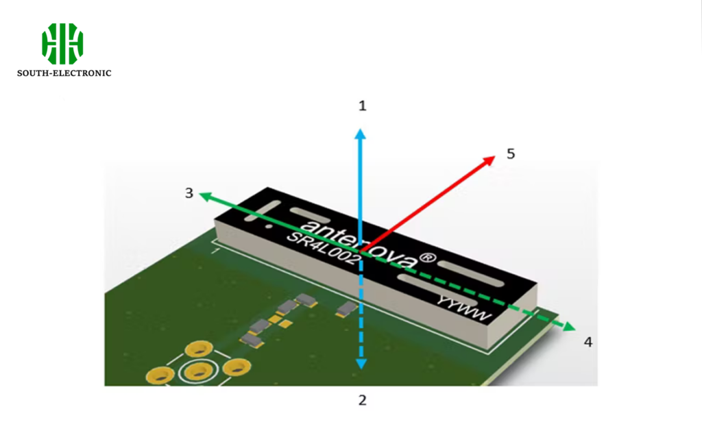
Use wavelength formulas like λ = c/f where c=speed of light and f=your target frequency (e.g., 2.4GHz). Add dielectric constant adjustments for precision.
Critical Factors in Antenna Sizing
Dimensions directly affect resonant frequency. Follow three rules:
Key Variables
| Variable | Impact | Example Value |
|---|---|---|
| Frequency | Sets base wavelength | 2.4 GHz |
| Dielectric Constant (εr) | Shrinks antenna size | 4.3 (FR4) |
| Substrate Height | Changes impedance | 1.6 mm |
First, calculate free-space wavelength (θ = 300/f). For 2.4GHz, θ=125mm. Next, adjust using εr: effective θ drops to θ/√εr. Final length is 50-70% of this value. Thin substrates need longer traces. Test iteratively with a VNA.
Which PCB Materials Boost Antenna Efficiency?
Losing signal from inefficient materials? Poor substrates drain power. Pick materials that amplify performance.
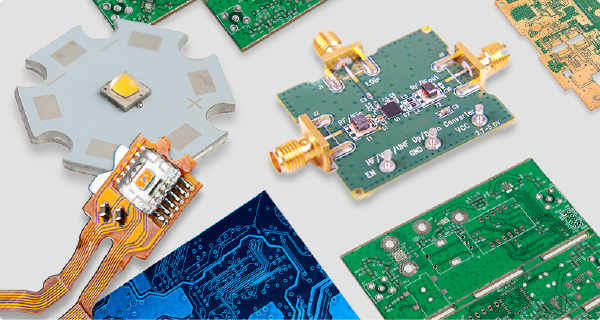
High-frequency laminates like Rogers 4350B improve efficiency. Low-loss tangents (<0.004) stop energy waste, unlike cheaper FR4.
Material Tradeoffs for Antenna Performance
Lossy materials cripple signals. Focus on three aspects:
Material Impact Comparison
| Material Type | Loss Tangent | Efficiency Gain | Cost |
|---|---|---|---|
| Standard FR4 | 0.02 | Low | $ |
| Rogers RO4003 | 0.0027 | 35% Higher | $$$ |
| PTFE-Based | 0.001 | Best | $$$$ |
Rogers laminates cut heat loss. This boosts gain by 1-3dB in shark fin antennas. PTFE works for radar applications but costs more. I use FR4 for prototypes but switch to Rogers for production. Consistent εr avoids frequency drift. Match copper weight (1oz+) to reduce ohmic loss.
Can Your PCB Antenna Survive Mass Production?
Seeing antenna failures after scaling up? Tiny flaws snowball in volume. Design for manufacturing resilience.
Avoid monopole detuning in batches. Set ±0.1mm tolerances, automated impedance tests, and stress-simulate worst cases pre-production.

Production-Proofing Your Antenna
Process variations break designs. Solve three challenges:
Risk Mitigation Table
| Failure Risk | Cause | Prevention |
|---|---|---|
| Impedance Shift | Etching errors | 100% Automated Optical Inspection (AOI) |
| Resonance Drift | Substrate εr variance | Batch consistency testing |
| Soldering Damage | Thermal stress | Reflow profiling under 240°C |
Test 20% more samples than standard PCBs. Shark fin antennas need corner stress analysis. I add keep-out zones near bends. Partner with manufacturers early for design reviews.
Conclusion
Choose PCB antenna types like monopole or shark fin wisely. Optimize dimensions, materials, and tolerance controls for reliable performance.

